FC6A S
ERIES
MICROS
MART
U
SER
’
S
M
ANUAL
FC9Y-B1722 9-9
9: A
NALOG
I/O M
ODULES
(7) Data
Data refers to the input analog values converted to digital values at the interval of the sampling time.
The data is written to data registers in the END processing of each scan. The analog input data is updated regardless of whether
the FC6A Series MICROSmart is stopped or running. The data is not guaranteed when the status (8) is a value other than "0".
For details on when PTC thermistor (threshold) is selected for the signal type, see "PTC Thermistor (Threshold)" on page 9-10.
(8) Status
The status of the analog input data (7) is stored in data registers.
Status Description
0Operating normally
1 Converting data
2 Initializing
3 Parameter setting error
4 Hardware fault (external power supply error)
5 Wiring fault (out of maximum range)
*1
6 Wiring fault (out of minimum range)
*1
7Reserved
8 When the analog input value is greater than 20 mA and less than the upper limit value
*2
9 When the analog input value is greater than the lower limit value and less than 4 mA
*3
10 to 65,535 Reserved
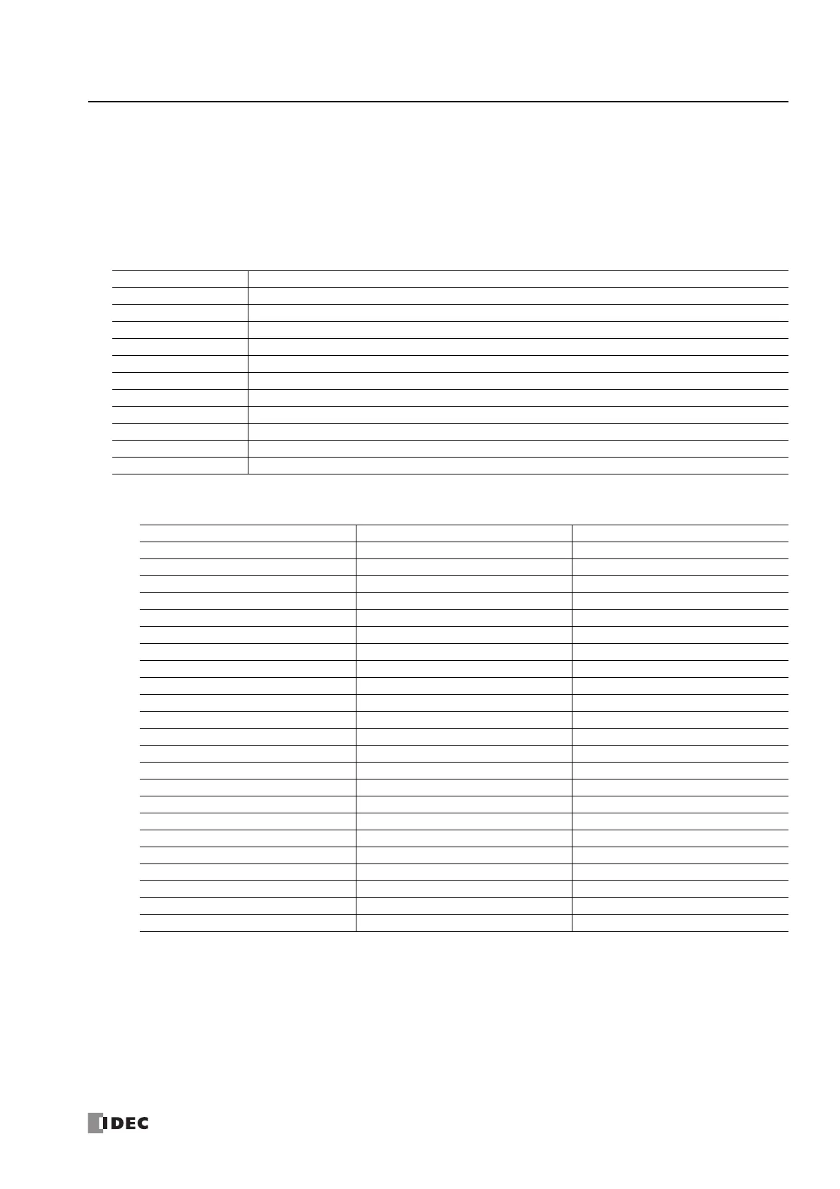
*1 When the analog input value is the upper limit value in the below table or higher, the out of maximum range error occurs. When the analog
input value is the lower limit value in the below table or lower, the out of minimum range error occurs.
Signal Type Lower Limit Value Upper Limit Value
0 to 10 V -0.2 V 10.2 V
-10 to +10 V -10.4 V 10.4 V
0 to 20 mA -0.4 mA 20.4 mA
4 to 20 mA 3.68 mA 20.32 mA
Type K thermocouple -200.0°C 1,300.0°C
Type J thermocouple -200.0°C 1,000.0°C
Type R thermocouple 0.0°C 1,760.0°C
Type S thermocouple 0.0°C 1,760.0°C
Type B thermocouple 0.0°C 1,820.0°C
Type E thermocouple -200.0°C 800.0°C
Type T thermocouple -200.0°C 400.0°C
Type N thermocouple -200.0°C 1,300.0°C
Type C thermocouple 0.0°C 2,315.0°C
Pt100 -200.0°C 850.0°C
Pt1000 -200.0°C 600.0°C
Ni100 -60.0°C 180.0°C
Ni1000 -60.0°C 180.0°C
NTC thermistor -90.0°C or 200 kΩ
*4
150.0°C or 100 Ω
*5
PTC thermistor 100 Ω 10 kΩ
PTC thermistor (threshold) 100 Ω 10 kΩ
Resistance measurement 100 Ω 32 kΩ
Expansion 0 to 20 mA -0.4 mA 23.54 mA
Expansion 4 to 20 mA 1.20 mA 23.17 mA
*2 Expansion 0 to 20 mA or expansion 4 to 20 mA only
*3 Expansion 4 to 20 mA only
*4 Out of minimum range error occurs when a resistance of 200 kΩ or higher is connected.
*5 Out of maximum range error occurs when a resistance of 100 Ω or lower is connected.

 Loading...