FC6A S
ERIES
MICROS
MART
U
SER
’
S
M
ANUAL
FC9Y-B1722 9-17
9: A
NALOG
I/O M
ODULES
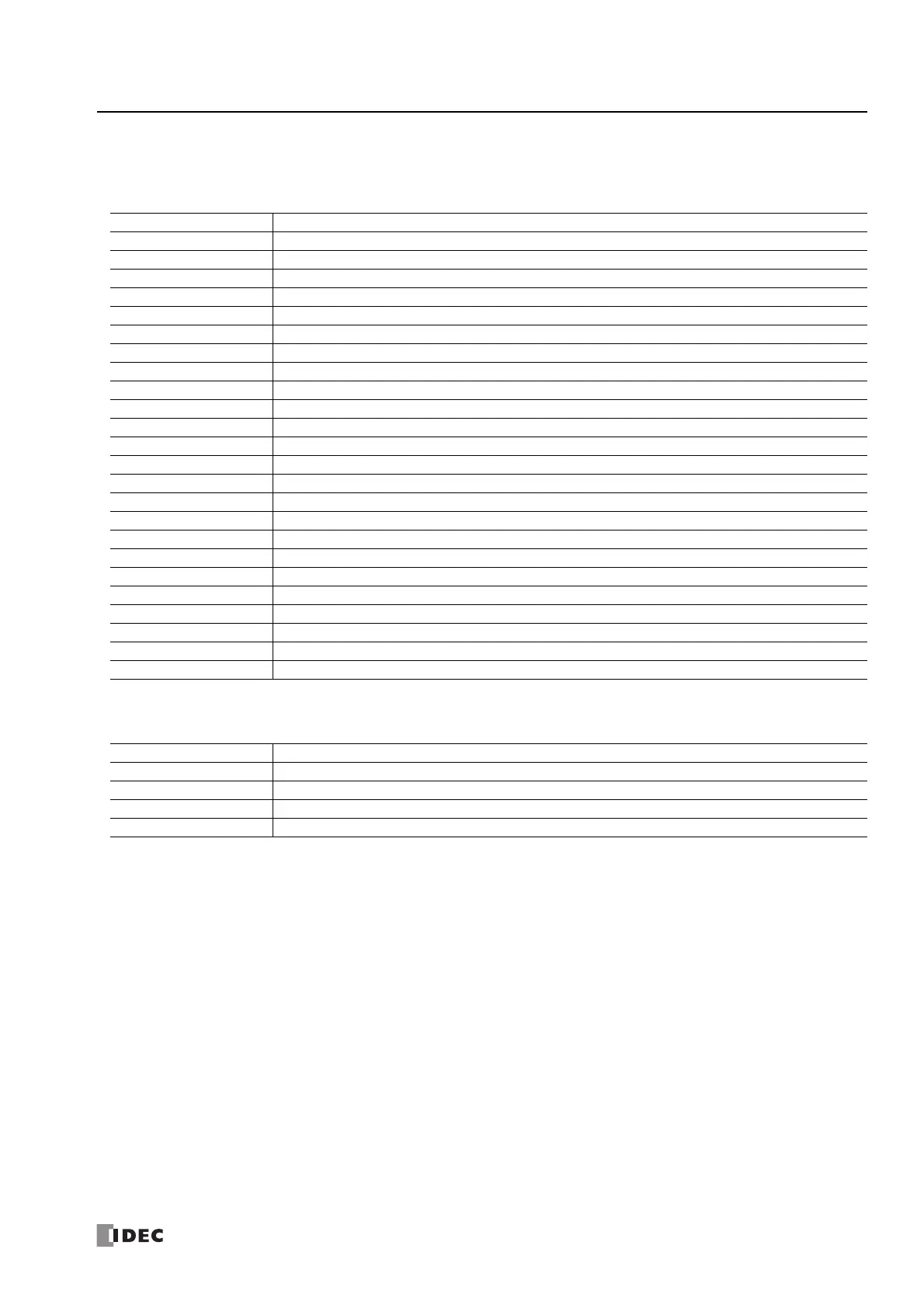
Analog Input Parameter Setting Values
The parameter setting values are as follows.
Signal type
If the setting value is outside the range, a parameter setting error will occur.
Data type
If the setting value is 4 to 65,535, a parameter setting error will occur.
Minimum and maximum values
The minimum and maximum values can be set only when the data type is set to optional range. Set the minimum and maximum
values between -32,768 and 32,767. However, when the signal type is set to PTC thermistor (threshold), set the minimum and
maximum values between 100 and 10,000.
Setting Value Signal Type
0Unused
1 0 to 10 V
2 -10 to +10 V
3 0 to 20 mA
4 4 to 20 mA
5Type K thermocouple
6Type J thermocouple
7Type R thermocouple
8Type S thermocouple
9Type B thermocouple
10 Type E thermocouple
11 Type T thermocouple
12 Type N thermocouple
13 Type C thermocouple
14 Pt100
15 Pt1000
16 Ni100
17 Ni1000
18 NTC thermistor
19 PTC thermistor
20 PTC thermistor (threshold)
21 Resistance measurement
22 Expansion 0 to 20 mA
23 Expansion 4 to 20 mA
Setting Value Data type
0 Binary data/Binary data (12 bits)
1 Optional range/Optional range (12 bits)
2 Celsius/resistance/Binary data (16 bits)
3 Fahrenheit/Optional range (16 bits)

 Loading...