20
ifm Programming Manual ecomatmobile BasicController (CR0403) Runtime System V03.02 2015-04-01
System description Hardware description
>
Output group Q0 (OUT0, OUT1)
14583
These outputs are a group of multifunction channels.
These outputs provide several function options (each output separately configurable):
• binary output, plus switching (BH) with diagnostic function and protection
• analogue current-controlled output (PWMi)
• analogue output with Pulse Width Modulation (PWM)
→ chapter Possible operating modes inputs/outputs (→ page 207)
► Configuration of each output is made via the application program:
→ FB OUTPUT (→ page 180)> input MODE
PWM output: → FB PWM1000 (→ page 182)
Current control and load current indication → FB CURRENT_CONTROL (→ page 178)
► For the limit values please make sure to adhere to the data sheet!
>
Diagnosis: binary outputs (via current and voltage measuring)
19433
19434
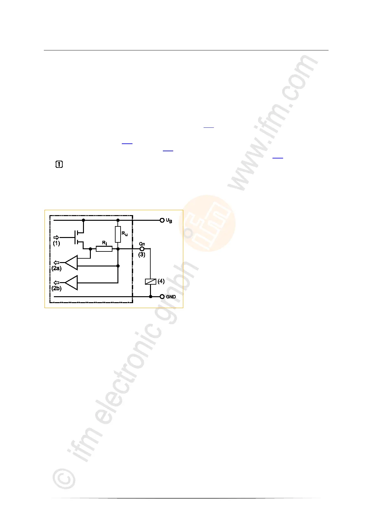
The diagnostics of these outputs is made via internal current and voltage measurement in the output:
Figure: principle block diagram
(1) Output channel
(2a) Read back channel for diagnosis via current measuring
(2b) Read back channel for diagnosis via voltage measuring
(3) Pin output n
(4) Load
>
Diagnosis: overload
19437
15249
Overload can only be detected on an output with current measurement.
Overload is defined as ...
"a nominal maximum current of 12.5 %" according to the data sheet.
>
Diagnosis: wire break (via current measurement)
19435
19400
Wire-break detection is done via the read back channel. When the output is switched (Qn=TRUE) wire
break is detected when no current flows on the resistor Ri (no voltage drops). Without wire break the
load current flows through the series resistor Ri generating a voltage drop which is evaluated via the
read back channel.
>
Diagnosis: wire break (via voltage measurement)
19436
19404
Wire-break detection is done via the read back channel. When the output is blocked (Qn=FALSE) wire
break is detected when the resistor Ru pulls the read back channel to HIGH potential (VBB). Without
the wire break the low-resistance load (RL < 10 kΩ) would force a LOW (logical 0).
 Loading...