11
UK
1 2
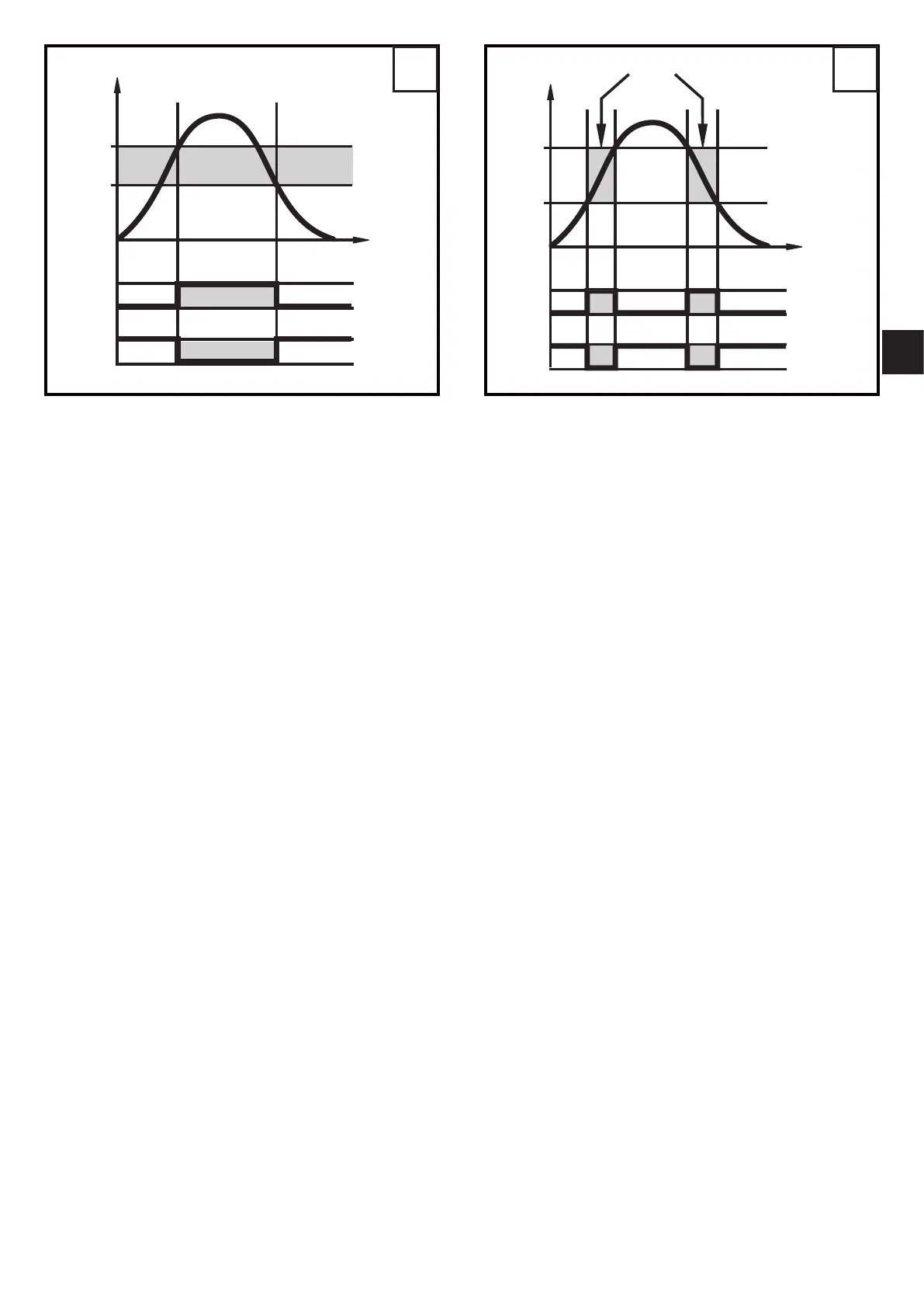
L = level; HY = hysteresis; FE = window
For the switching output a switch-off delay of max� 5 s can be set (e�g� for •
especially long pump cycles)�
Offset for indicating the real level in the tank
The zone between tank bottom and lower edge of the probe can be entered as
offset value [OFS]� So display and switch points refer to the actual level�
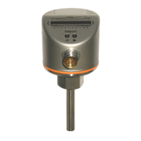
Probes for different tank heights
The unit can be installed in tanks of different sizes� Probes in different lengths •
are available� To adapt to the tank height, each probe can be shortened� The
minimum probe length is 10 cm, the maximum probe length is 160 cm�
Probe and housing can be rotated without restriction� This enables easy instal-•
lation and orientation of the head of the unit after installation�
Safe state
In case of a fault a safe state can be defined for each output�•
If a fault is detected or if the signal quality is below a minimum value, the out-•
puts pass into the "safe state"� For this case the response of the outputs can be
set via the parameters [FOU1], [FOU2]�
Temporary loss of signal caused e�g� by turbulence or foam formation can •
besuppressedbyadelaytime(→10.5.8[dFo]).Duringthedelaytimethe
last measured value is frozen� If the measured signal is received again with
sufficient strength within the delay time, the unit continues to work in normal
operation� If, however, it is not received again with sufficient strength within the
delay time, the outputs pass into the safe state�