10
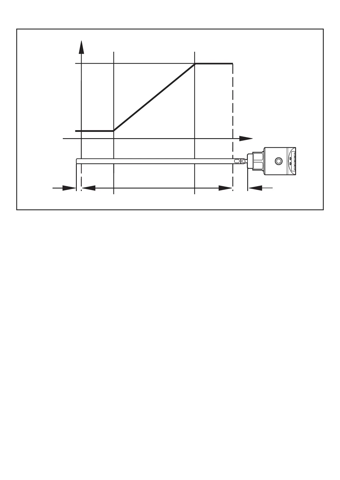
Curve of the analogue signal: (Measuring range scaled):
I [mA]
U [V]
L
S2
S1
A
ASP AEP
I1 I2
L = level; ASP = analogue start point; AEP = analogue end point
A=activezone;I1=inactivezone1;I2=inactivezone2(→12Scaledrawing)
S1 = zero signal (4 mA / 0 V); S2 = full signal (20 mA / 10 V)
Note the tolerances and accuracy limits during the evaluation of the analogue
signal(→13Technicaldata).
Switching functions
The unit signals via the switching output OUT1 that a set limit level has been
reached or that the level is below the limit value�
For the output the following switching functions can be selected:
Hysteresis function / normally open (figure 1): [OU1] = [Hno]�•
Hysteresis function / normally closed (figure 1): [OU1] = [Hnc]�•
First the set point (SP1) is set, then the reset point (rP1) with the requested
difference�
Window function / normally open (figure 2): [OU1] = [Fno]�•
Window function / normally closed (figure 2): [OU1] = [Fnc]�•
The width of the window can be set by means of the difference between FH1
and FL1� FH1 = upper value, FL1 = lower value�