13
UK
If analogue signal current (I) is selected in the menu under OU2 and the
output is not connected (resistor = infinite), the error message W532 is
displayed in intervals. The measuring result is not affected by this.
► Alternatively: change OU2 to switching output.
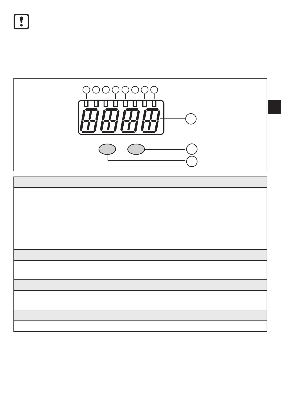
7 Operating and display elements
10
9
11
Mode/Enter Set
1 2 3 4 5 6
7
8
1 to 8: Indicator LEDs
- LED 1 to LED 5 = system pressure in the specified unit of measurement.
- LED 6 = system pressure in % of the scaling of the analogue output (range ASP to AEP)
if [OU2] is configured as analogue output.
System pressure in % of the final value of the measuring range if [OU2] is configured as
switching output.
- LED 7 = switching status OUT2 (lights when output 2 is switched).
- LED 8 = switching status OUT1 (lights if output 1 is switched).
9: Alphanumeric display, 4 digits
- Display of the current system pressure.
- Indication of the parameters and parameter values.
10: Set button
- Setting of the parameter values (scrolling by holding pressed; incrementally by pressing
once).
11: Mode/Enter button
- Selection of the parameters and acknowledgement of the parameter values.