2. Installation – Linking System 11
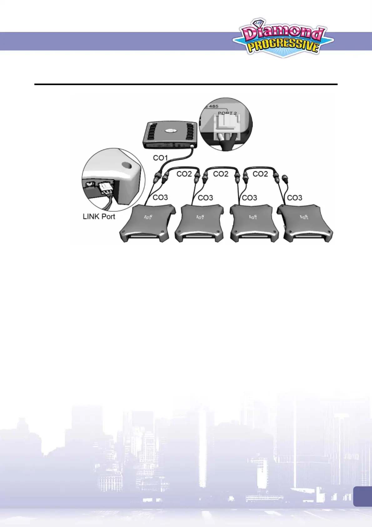
2.2 Connecting Control Box to PC Boards
Refer to the diagram above and use CO1, CO2 and CO3 signal cords to connect the control box
to PC boards.
Adjust DIP SW1 Settings for linking mode
To use Linking Mode, all the PC boards’ DIP SW1 must be correctly adjusted:
On all the PC boards, set No.8 of DIP SW1 to use
Link Mode
.
Use No.1~ 5 of DIP SW1 to set each PC board to use different slave ID.
For details on DIP SW settings, refer to
<4.2 PC Board>
section.