Page 58 AMAZON2 SERIES Operation Manual
Pioneer in Digital Vision Technology
5.8. PIO Control Register
The Programmed Input / Output provides a set of I/O ports which can be configured by the defined address. The
PIO control register address, for strobe and trigger signal, is as follows.
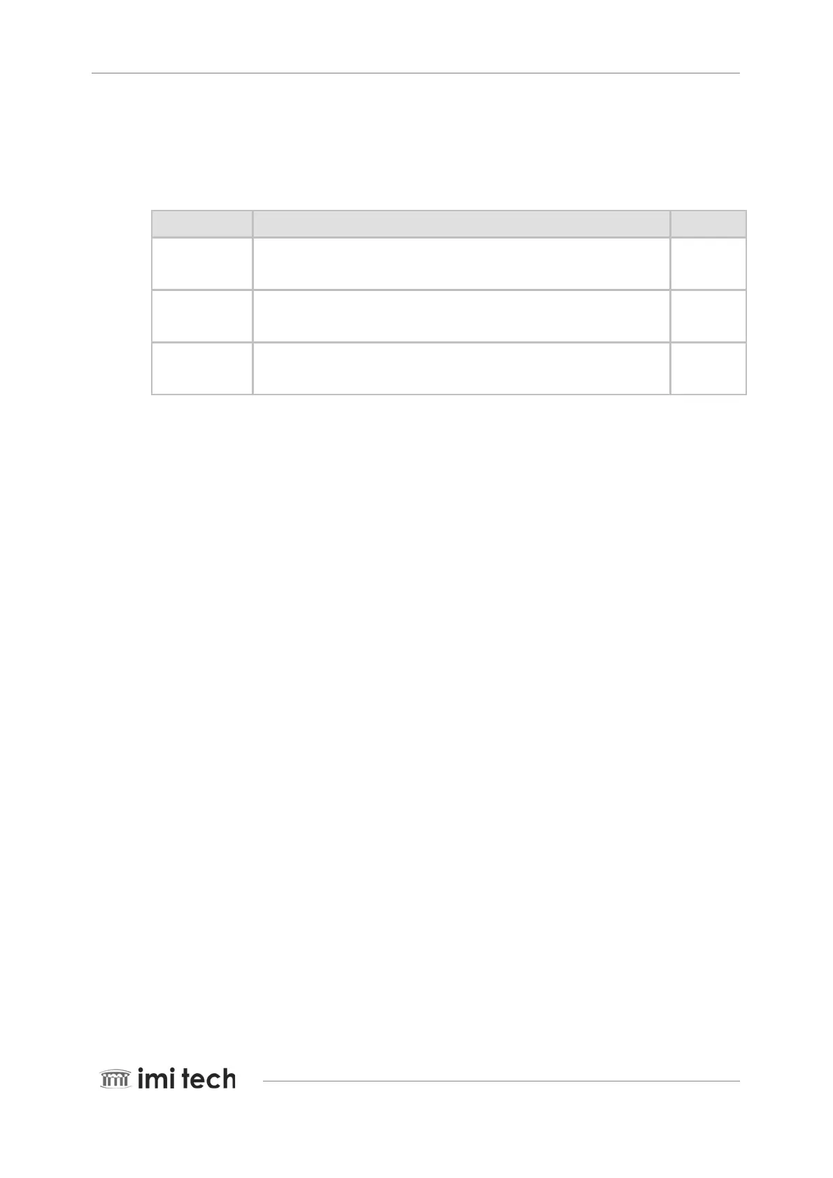
Address Description (bit 0: msb) Read/Write
0xF2F21000
PIO output register
Bit 30: Strobe GPIO output
Write only
0xF2F21004
PIO input register
Bit 31: Trigger GPIO input
Read only
0xF2F21008
PIO GPIO enable register.
Bit 30: Strobe pin GPIO selector (1: GPIO, 0: strobe)
Read/Write