Chapter 3 Environment description and installation
3-16
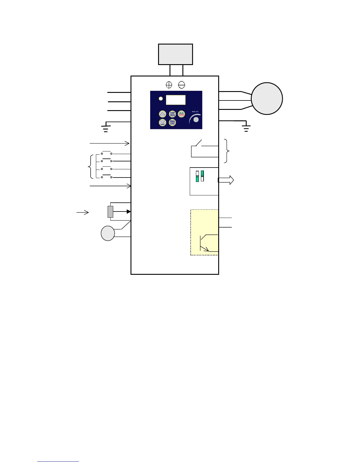
3.5 iDrive EDX connection diagram
(3) 24V
10kΩ
Note 1:- Connect point ‘x’ to either: -
Terminal (3) (internal +24Vdc) for PNP mode (positive switching) OR…
Terminal (8) (Common 0V) for NPN mode (negative switching).
Note2:- External 24Vdc may be used to supply the external contacts at point ‘x’.
If so then connect the 0V of the external supply to Common (terminal 8).
‘x’
L1(L)
L2
L3(N)
T1
T2
T3
Motor
(4) S1
(5) S2
(6) S3
(7) S4
(8) COM
(9) 10V
(10) AIN
(11) COM
(12) FM+
1 2
FM
1.SW1: Digital signal selection (NPN/PNP)
2.SW2: Control signal selection
(0~10Vdc / 4~20mA)
RA