Chapter 5 Trouble shooting and maintenance
5-4
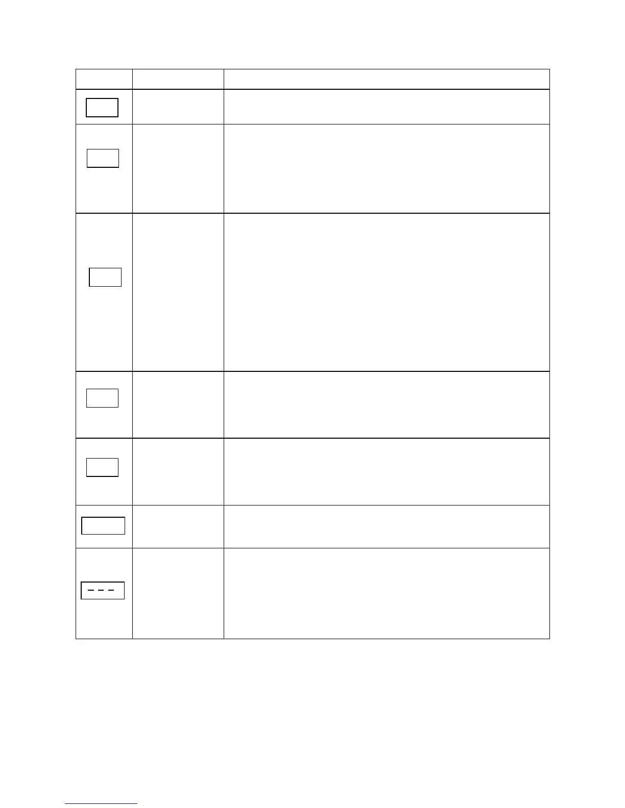
5.1.2 Set up & Interface Errors.
Display Error Description
Zero speed stop Displayed when set frequency <0.1Hz
Fail to start
directly
1. If the inverter is set to external control mode (A00 = 001),
and direct start is disabled (b33=001), the inverter cannot be
started and will flash STP1 when Run command in ON when
power is applied (see descriptions of b33).
2. Direct start is possible when b33 = 000.
Keypad
emergency stop
1. If the inverter is set to external control mode (A00=001) the
inverter will stop according to the setting of b92 when stop
key is pressed. STP2 flashes after stop. Turn the Run switch
to OFF and then ON again to restart the inverter.
2. If the inverter is in communication mode and Stop key is
enabled, the inverter will stop as set by b92 when Stop key is
pressed during operation and then flashes STP2.
The PLC must send a Stop command followed by a Run
command to the inverter for it to be restarted.
External
emergency stop
The inverter will decelerate to stop and then flashes E.S. when
there is an external emergency stop signal via the
multi-function input terminals (see descriptions of b35 ~ b38).
External base
block
The inverter stops immediately and then flashes b.b. when
external base block is input through the multi-functional input
terminal (see descriptions of b35 ~ b38).
PID feedback
broken
PID feedback signal circuit error detection
REMOTE
KEYPAD cable
broken
1. REMOTE KEYPAD is not connected with inverter, such a
display will occur.
2. REMOTE KEYPAD and main KEYPAD both display such
signal means communication error.
b.b.
PID
SP2
E.S.
SP1
SP0