Chapter 3 Environment description and installation
3-17
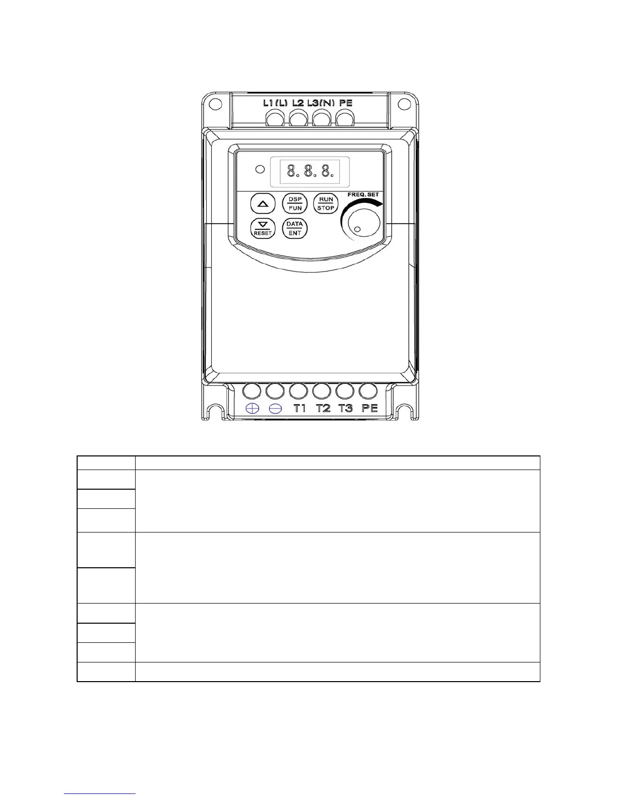
3.6 Description of Inverter Terminal
Descriptions of power terminals
Symbol Description
L1 ( L )
L2
L3 ( N )
Main power input Single-phase: L/N
Three-phase: L1/L2/L3
⊕
⊖
DC link and braking unit terminals.
Never connect resistors directly to these terminals or damage will occur!
T1
T2
T3
Inverter output.
Connect appropriate 3-phase AC induction motor to these terminals.
PE Earth / Ground terminals (2 points)
* Brake units are required for applications where a load with high inertia needs to be stopped rapidly.
Use a correctly rated braking unit and resistor(s) to dissipate the energy generated
by the load during stopping, otherwise inverter will trip on over-voltage.
IMO