Chapter 3 Environment description and installation
3-18
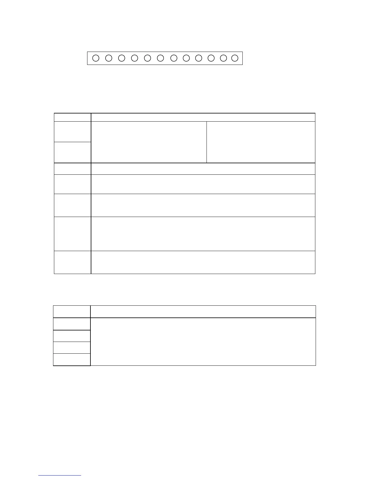
Control signal terminals block description
1 2 3 4 5 6 7 8 9 10 11 12
TM2
Symbol Description
RA
RB
Multi-functional output terminals
Normally open relay contacts SPST
Rated contact capacity:
(250VAC/10A resistive)
(refer to b55 for functions)
10V +10Vdc supply for external potentiometer for speed reference.
AIN Analog frequency command input terminal or multi-function input terminal S7
(high level: >8V / low level: <2V, (refer to b41 description)
24V
PNP (SOURCE) input, S1~S4 (S5/S6/S7) common terminal.
Set SW1 to ‘PNP’ position. Connect option card power supply if required.
COM
NPN (SINK) input, S1~S4 (S5/S6) common terminal.
Set SW1 to ‘NPN’ position. Connect option card power if required.
Use this terminal for analogue input and analogue output signals - common.
FM+
Multi-function +ve analog output terminal, (refer to b53 description).
Output signal: 0-10Vdc proportional to b53 setting.
Symbol Description
S1
S2
S3
S4
Multi-function input terminals (refer to b35~b38 descriptions)
RA
RB
24V
S1
S2
S3
S4
COM
10V
AIN
COM
FM+