3 Description of Functions and Measuring Principle User Manual PROFview XL
Glitch error:
Bits for which the voltage has been fallen below the reference voltage for at least 1/8th of the bit time and has
then recovered
Edge errors:
Bits for which the edge rise or fall time is more than 3/8th of the bit time
Level errors:
Bits for which the value of the reference voltage is not reached
Sporadically occurring faults at the frames to be measured are indicated via the error counters for glitch,
edge and level. Any permanent faults, however, will reduce the quality level.
Note:
The value of the quality level is equivalent to the "minimum signal level" of the PROFview.
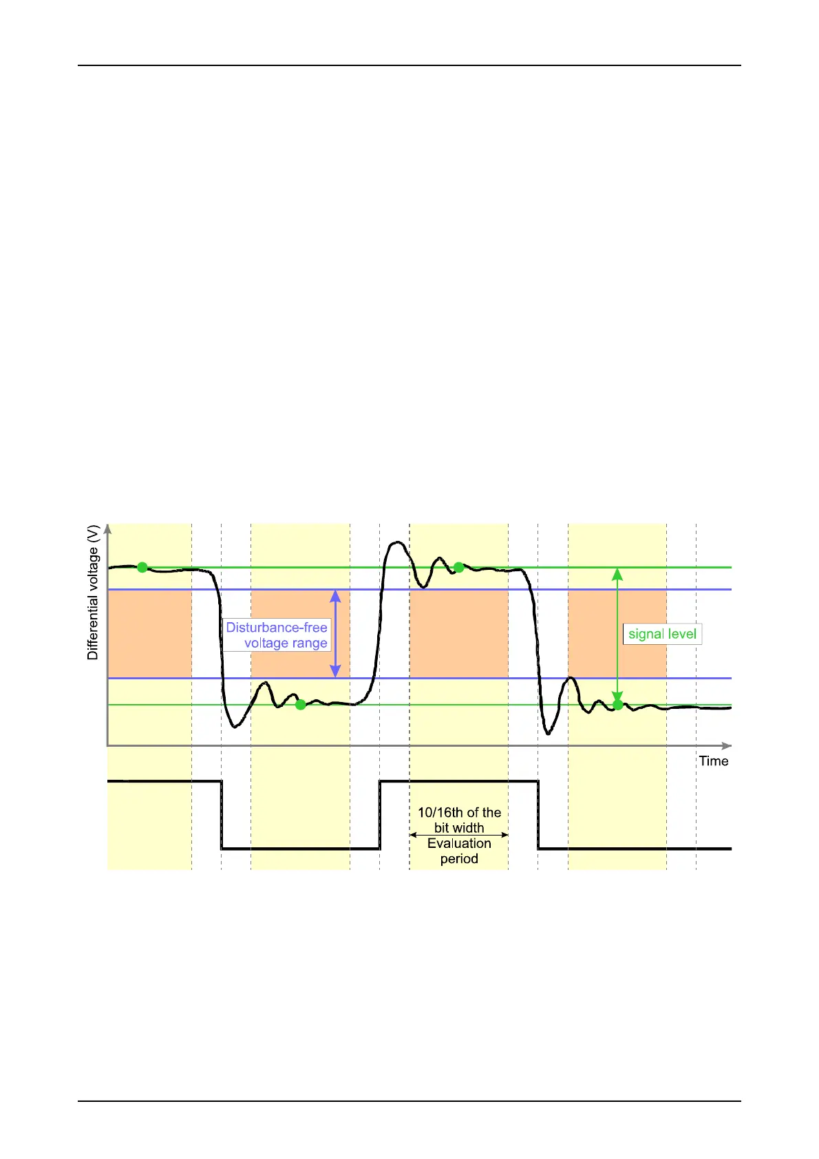
3.2.2 Disturbance-free voltage range
The term 'disturbance-free voltage range' is used to denote the interference-free range of the differential volt-
age, which is determined over a certain part of each bit of the frames for the station to be measured (relevant
frames). This part is called evaluation period.
Each bit is sampled 16 times. The disturbance-free voltage range is evaluated over 10/16th of the bit width
(62.5 % of the evaluation period). At both the beginning and end of each bit, 3/16th of the bit width are ex-
cluded from the determination of the disturbance-free voltage range (see Fig. 2). Signal overshoot and sett-
ling processes are excluded from the interference voltage measurement, as long as they lie outside the eval-
uation period. A voltage drop of less than 1/16th of the bit time during the evaluation period cannot be detect-
ed reliably and thus also has no influence on the determination of the disturbance-free voltage range.
6 PROFview XL
Fig. 2: Measuring principle for disturbance-free voltage range and signal level