IDS440 Users Manual version 4.2
53
Hardware and Wiring
This section describes installation and wiring information for the interface ports. There
are two bi-directional serial ports, one parallel port with TTL inputs and outputs, and one
load cell input port. The serial ports are used to interface to a printer and to a host device
or PC for continuous output. The parallel port is used to interface to parallel printers and
for remote switch input and relay control using the TTL I/O. The load cell input is used
to interface to the scale platform.
Load Cell Connector - TB3
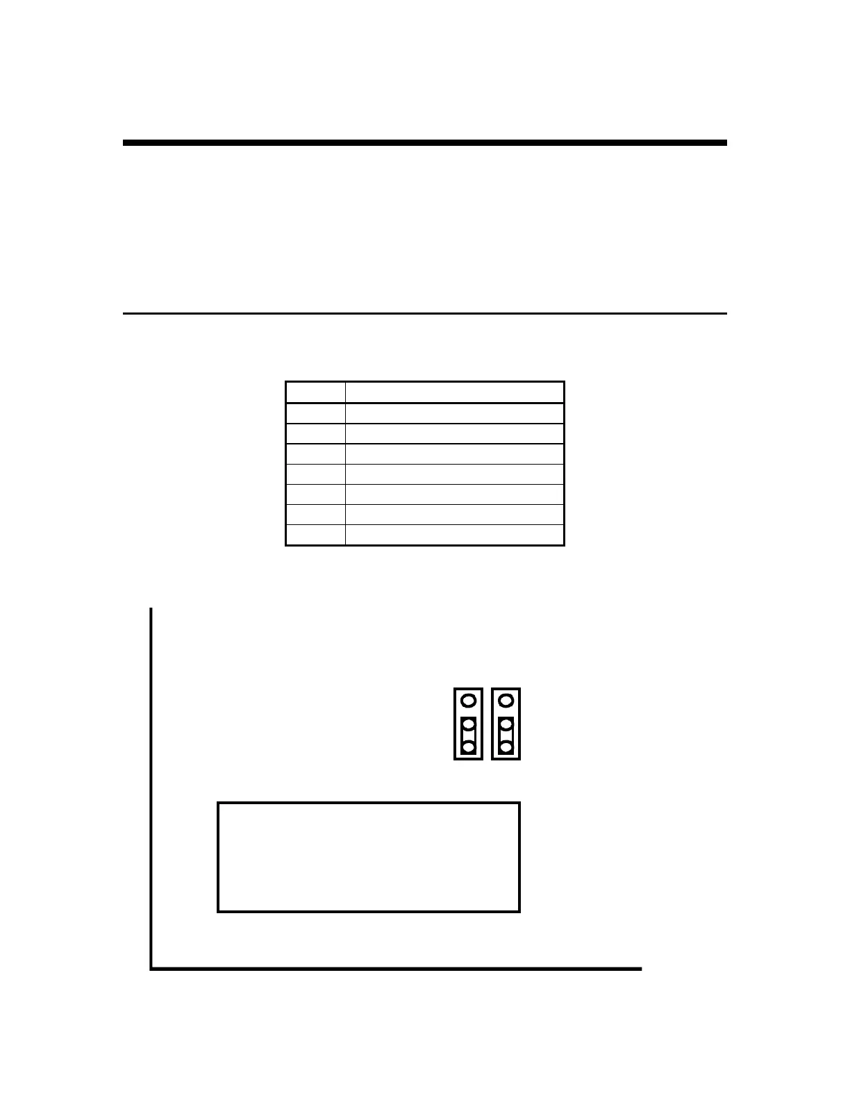
NOTE: JP1 and JP2 on the circuit board can be used to disable remote sensing.
Load Cell - TB3
Pin #
Signal Name
1 + Signal
2 - Signal
3 + Excitation
4 + Sense
5 - Sense
6 - Excitation
7 Analog ground
JP1
JP2
TB3
Remote Sense Jumpers - Remote sense DISABLED
Place jumpers as shown to DISABLE remote sense. Move jumpers up to
enable remote sense.