EasyManuals Logo

INIM Electronics SmartLine Series User Manual

INIM Electronics SmartLine Series
72 pages
To Next Page IconTo Next Page
To Previous Page IconTo Previous Page
Page #26 background imageLoading...
Page #26 background image
26 User interface
Conventional fire detection control panel
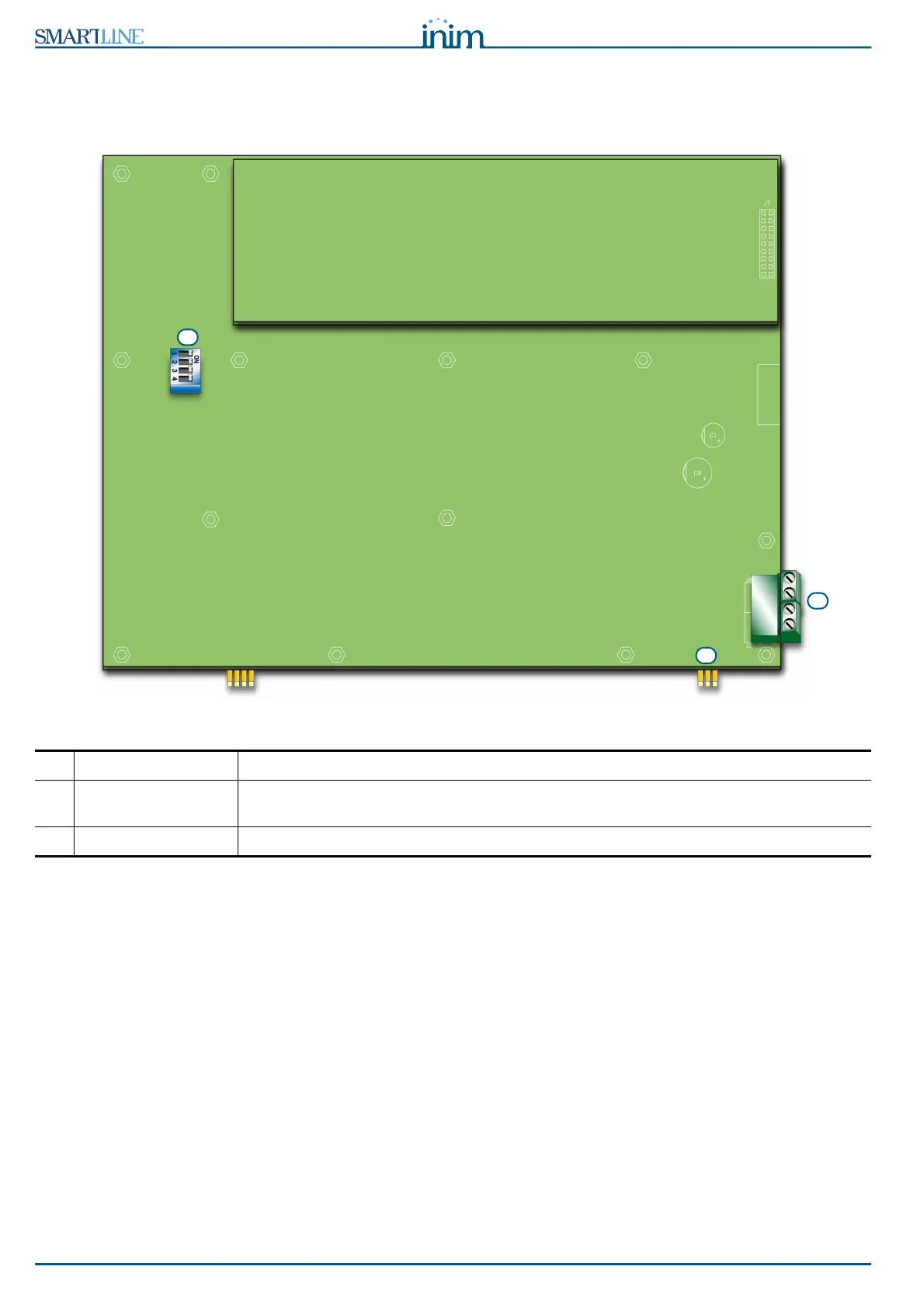
5.2.3 Repeater board
If you open the repeater enclosure, the rear side of the electronic board (which is attached to the
frontplate) will be on view. Following is a description of the parts which will be used during the installation
phase:
Figure 10 - The rear side of the repeater board
[A] DIP switches For the repeater address setting
[B] RS485 terminals From the bottom of the figure to the top ā€œ+24V - + GNDā€; for the connection to the
RS485 BUS
[C] EOL terminals For the setting jumper which indicates the position of the repeater in the system.
C
A
B

Table of Contents

Questions and Answers:

Question and Answer IconNeed help?

Do you have a question about the INIM Electronics SmartLine Series and is the answer not in the manual?

INIM Electronics SmartLine Series Specifications

General IconGeneral
BrandINIM Electronics
ModelSmartLine Series
CategoryControl Panel
LanguageEnglish

Related product manuals