Copyright Innovative Technology Ltd 2008 GA333-5
Pin Name Description
1 Vend 1
Open Collector Output. Function changes depending on Machine
Interface Protocol. (See individual interface descriptions for
details) Also the Pulse Stream output. Also the serial Output pin
in SSP Serial Mode, and other serial modes.
2 Vend 2
3 Vend 3
4 Vend 4
Open Collector Outputs.
Function changes depending on Machine Interface Protocol.
(See individual interface descriptions for details)
5 Inhibit 1
Inhibit channel 1 by holding this pin HIGH. To Enable a channel
the inhibit must be held LOW Also the serial Input pin in SSP
Serial Mode, and other serial modes
6 Inhibit 2 Inhibit channel 2 by holding this pin HIGH
7 Inhibit 3 Inhibit channel 3 by holding this pin HIGH
8 Inhibit 4 Inhibit channel 4 by holding this pin HIGH
9 Busy NV10 is validating and stacking output. Active low while the
NV10 is reading, transporting or stacking a note.
10 Escrow Operate Escrow function by holding LOW
(see Appendix B for full details)
11 Factory
Use Only
Do not connect
12 Factory
Use Only
Do not connect
13 Factory
Use Only
Do not connect
14 Factory
Use Only
Do not connect
15 +Vin Nominal 12V DC supply
16 0V 0V supply
Table 5 – 16 Pin connector details
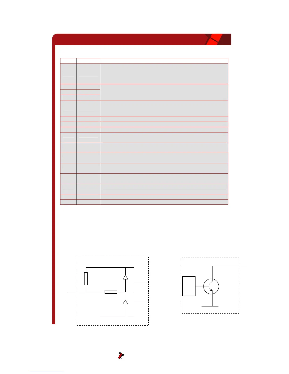
5.2 INPUT AND OUTPUT HARDWARE CIRCUITS
CAUTION: THE OUTPUT LOW SIGNAL IS AFFECTED BY THE VALUE OF THE PULL UP RESISTOR
ON THE HOST MACHINE INTERFACE. ENSURE YOUR SIGNAL LOW LEVELS COMPLY WITH THE
74HC CMOS SERIES SPECIFICATION FOR RELIABLE OPERATION (SEE FIGURE 4).
Figure 4 - Input and Output Circuits
NV10 Operations Manual