INDEX
INDEX OF TABLES
Table 1 – Environmental requirements 5
Table 2 – Power requirements 5
Table 3 – Switch 3 & 4 machine interface selection 8
Table 4 – LED status 9
Table 5 – 16 pin connector detail 10
Table 6 – Interface Logic Levels 11
Table 7 – Serial interface input and outputs 11
Table 8 – Receive and transmit codes 16
Table 9 – Example protocols 17
Table 10 – Parallel and Binary Pin Description 22
INDEX OF FIGURES
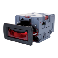
Figure 1 – The NV10 and universal bezel PA231 6
Figure 2 – NV10 user display and DIPswitches 7
Figure 3 – Internal connector 9
Figure 4 – Input and output circuits 10
Figure 5 – Typical Serial Output: Transmission of the value 20 (decimal),
Note not recognized
15
Figure 6 – Typical Serial Output: Transmission of the value 20 (decimal),
Note not recognized
18
Figure 7 – MDB Opto Isolated Input / Output circuits NV10 MDB Slave 19
Figure 8 – ccTalk connector pins on the NV10 21
Figure 9 – Cloning kit CK2 23
Figure 10 – Bezel and NV10 installation 25
Figure 11 – NV10 sensors 27
Figure 12 – NV10 belt access 28
Figure 13 – Cash box mounting location 33
Figure 14 – Dividing plate location for cash chute 33
Figure 15 – Escrow timing diagram for parallel vends 34
Figure 16 - Connecting DA1 to a NV10 and PC for updating 35
Figure 17 - Connecting DA2 to a NV10 and PC for upgrading Software
Installation
36
NV200 Operations Manual