(Slow = 1 second period)
In normal RUN operation, when the NV10 is
ready to read a note, the green status led will
flash slowly ("Heartbeat") to signal a
“healthy” status.
On Start Up - Flashing RED one
second period
one second period.
NV10 has a Transportation Error
somewhere in he note path
During operation - Flashing RED
Firmware fail
t
On Start Up - Fast flashing RED
(fast = half second period)
RED (fast = half second period)
NV10 can sensor(s)
may be blocked
During operation - Fast flashing
Dataset fail
not calibrate,
Permanent RED Memory has been corrupted
F Power supply is incorrect, check specification lashing AMBER and bezel lights
Alternating RED and GREEN Ei ll ther a safe jam or Cash box fu
Table 4
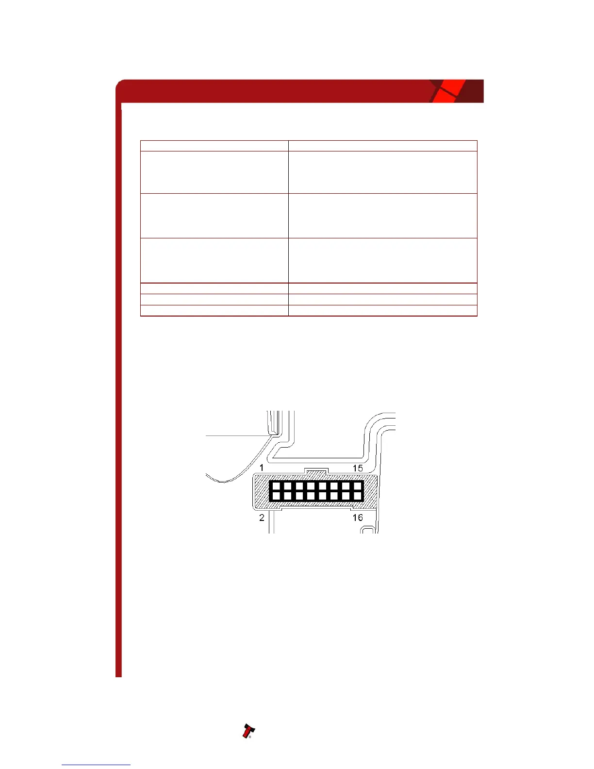
MACHINE INTERFACE: HA
e left side of the unit. It has 16 pins (see figure
), two are used for the 0v and +12v power supply and there are five outputs and five inputs,
Figure 3 - Interface Connector
.1 INTERFACE CONNECT
e connector pin details are described below (see table 5); they use an IDC 16-pin 0.1"
– LED Status Code
5 RDWARE
The NV10 interface connector is located on th
3
the remaining four pins are reserved for future use. An example mating connector is Molex
Part No: 39-51-2160
5
Th
OR PIN DETAILS
pitch header with 2 rows of 8 pins.
NV10 Operations Manual 9