12
NEA - ICU Montage- und Betriebsanleitung
NEA - ICU Mounting and Operating Instructions
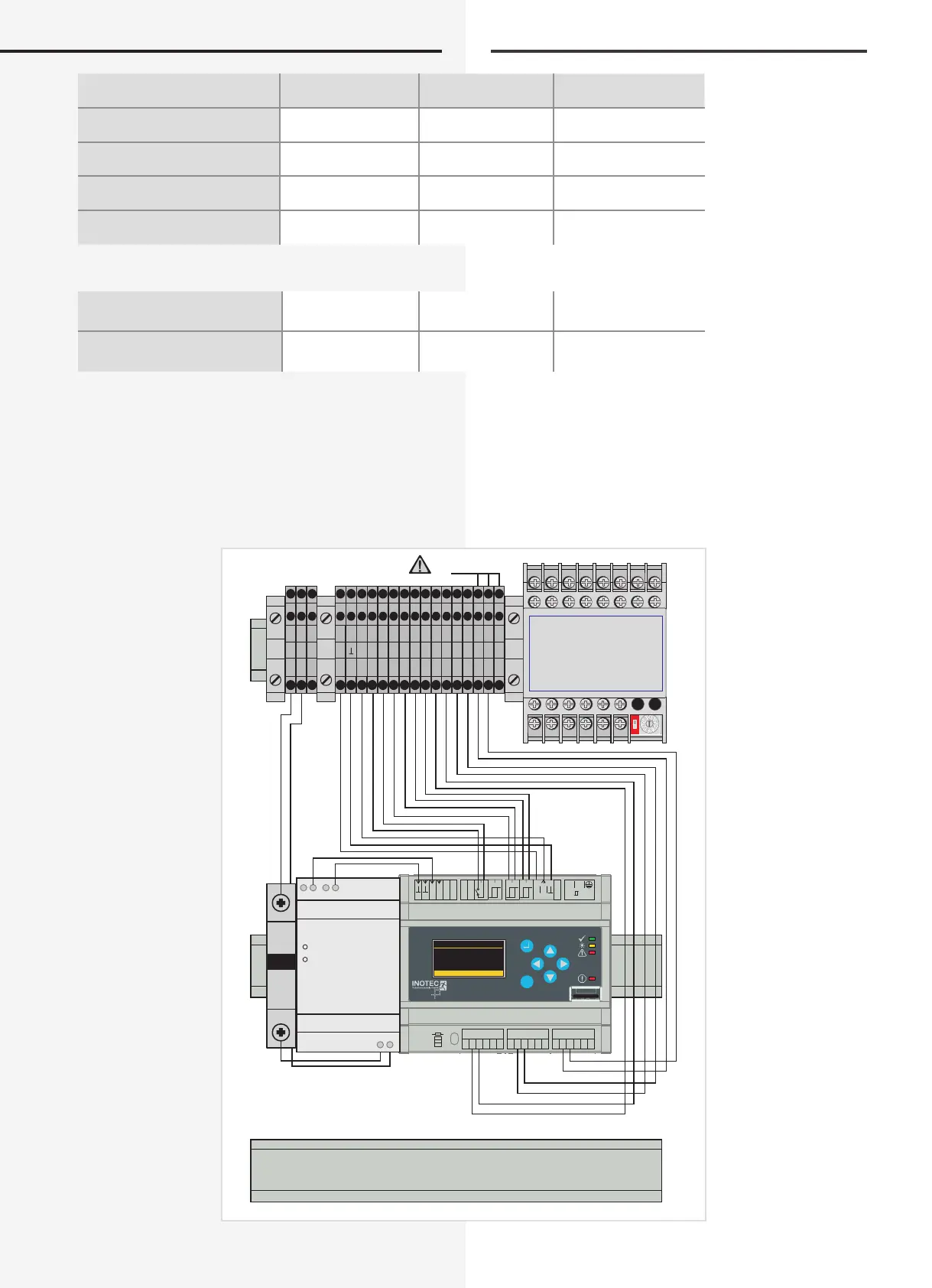
6.2. Electrical connection
The wiring at the NEA-ICU is done in the small distributor
from above. The save mains is connected to the termi-
nals L, N and PE.
All system components built into the small distribution
boards are pre-wired from the factory. At the output
terminals B - / B +, up to 99 addresses can be connected
per optional slot.
Schutzart
Protection category
2–reihig (HxBxT)
2-row (HxWxD)
3–reihig (HxBxT)
3-row (HxWxD)
1.
Aufputzgehäuse
surface mounting
IP30 370x305x96,5mm* 515x305x96,5mm*
2.
Aufputzgehäuse
surface mounting
IP65 427x310x151mm* 552x310x151mm*
3.
Unterputzgehäuse
ush mounting
IP30 505x348x94,5mm* 630x348x94,5mm*
4.
Hohlwandgehäuse
recessed wall mounting
IP30 505x348x94,5mm* 630x348x94,5mm*
*Außenmaße vom installierten Produkt Outside dimensions of the installed product
Nischenmaße UP
niche dimension
490x335x90mm 615x335x90mm
Ausschnittmaße HW
cut-out dimension
470x314,5x87mm 595x314,5x87mm
6.2. Elektrischer Anschluss
Die Verkabelung erfolgt bei der NEA-ICU im Installations-
kleinverteiler von oben. Das gesicherte Netz ist an den
Klemmen L, N und PE anzuschließen. Alle im Kleinver-
teiler eingebauten Systemkomponenten sind ab Werk
vorverdrahtet. Über die Abgangsklemmen B-/B+ können
je Optionsplatz bis zu 99 Teilnehmer angeschlossen
werden.
1 2 3 4 5 6 1 2 3 4 5 6 1 2 3 4 5 6
OPT 1 OPT 2
OPT 3
ON
OFF
CAN-BUS
V42+
V42+
H NAC
L NAC
H NAC
L NAC
B
1 2 3
+
IB
N L
HV 230~
ESC
22.08.2008 15:30
Status
NEA
Funktionen
Optionsplätze Optional slots
DC LOW
CP-D 24/1.3
DC ON
L N
+ + - -
optional RTG
L N
PE
+
IB 1 2 SL
+
SL
-
FS
+
FS
-
B- B+ B- B+ B- B+
Optional slot
Optionsplatz