9
NEA - ICU Montage- und Betriebsanleitung
NEA - ICU Mounting and Operating Instructions
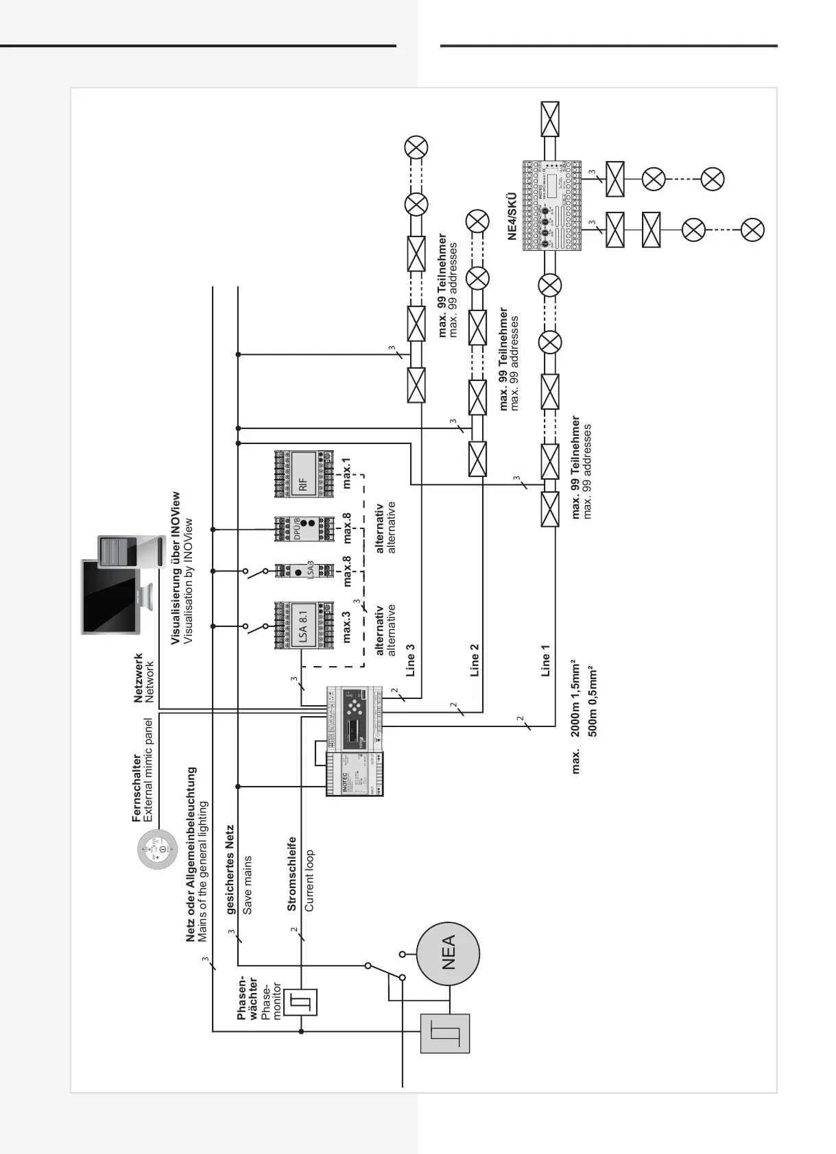
4.2. Systemschaltbild (Beispiel)
LSA 8.1 RIF
3
3
2
2
2
2
3
3
3
3
N L
+
-
INOTEC
Sicherheitstechnik GmbH
Am Buschgarten 17
D-59469 Ense
U : 230 V ~ 50/60 Hz
U : 183,5 - 260 V
I : 0,38 A
U : 48 V
I : 1 A
J : -5...+45°C
D.E.R
Power Supply
PSU 24
OUTPUTINPUT
ON
P/N : 965300
E
E
E
A
A
1 2 3 4 5 6 1 2 3 4 5 6 1 2 3 4 5 6
OPT 1 OPT 2 OPT 3
ON
OFF
CAN-BUS
V42+
V42+
H NAC
L NAC
H NAC
L NAC
B
1 2 3
+
IB
N L
HV 230~
ESC
22.08.2008 15:30
Status
NEA
Funktionen
NEA
3
3
3
DPÜ/B
LSA.3LSA.3
Betrieb
Aus/Off
Ein/On
Operation
Failure
-Operation
INOTEC
Betrieb
Störung
-Betrieb
Netz oder Allgemeinbeleuchtung
gesichertes Netz
Stromschleife
max.3 max.1
max. 2000m 1,5mm²
500m 0,5mm²
max. 99 Teilnehmer
max. 99 Teilnehmer
max.8max.8
NE4/SKÜ
Line 3
alternativ alternativ
Line 2
Line 1
Phasen-
wächter
max. 99 Teilnehmer
Visualisierung über INOView
Netzwerk
Fernschalter
Mains of the general lighting
Save mains
Current loop
max. 99 addresses
max. 99 addresses
max. 99 addresses
alternative alternative
Phase-
monitor
Visualisation by INOView
Network
External mimic panel
4.2. System diagram (example)