18
NEA - ICU Montage- und Betriebsanleitung
NEA - ICU Mounting and Operating Instructions
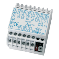
7.5. Fernmeldetableau – MTB
Das Fernmeldetableau wird an das RIF5-Modul und der
NEA-ICU gem. nachfolgendem Schaltbild angeschlos-
sen. Die Leitungslänge darf bei einem Querschnitt von
0,5mm² maximal 500m betragen.
Auf der Frontseite des MTB sind 3 Leuchtdioden und ein
Schlüsselschalter angeordnet:
• Grün Betrieb
• Gelb Batteriebetrieb
• Rot Störung
Schalterstellung EIN / AUS die Anlage wird blockiert /
nicht blockiert
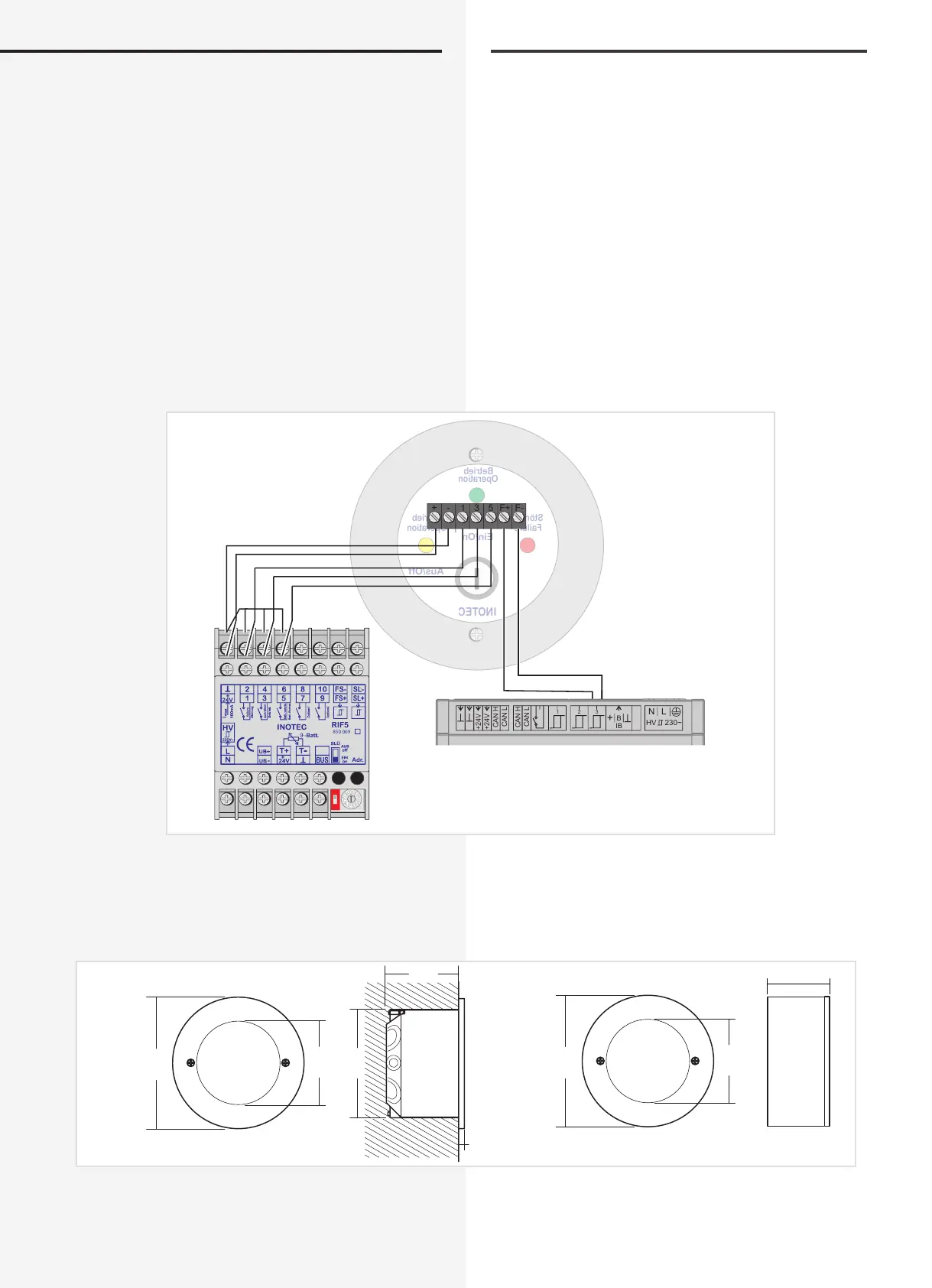
Technische Daten:
Montage: Auf- / Unterputz
Schutzart: IP 30
Gehäuse: Edelstahl/Aluminium velour lackiert
Aus/Off
Ein/On
Operation
Failure
-Operation
INOTEC
Betrieb
Störung
-Betrieb
V42+
V42+
H NAC
L NAC
H NAC
L NAC
B
1 2 3
+
IB
N L
HV 230~
ESC
22.08.2008 15:30
Status
NEA
Funktionen
Unterputz / Built-in
6,5 mm
90 mm
58 mm
74 mm
50 mm
Aufputz / Wall-mounted
90 mm
58 mm
43 mm
7.5. Remote mimic panel — MTB
The remote mimic panel is connected to the RIF5
module and the NEA-ICU in accordance with the circuit
diagram below. The wire length may be amaximum of
500m with a cross-section of 0.5 mm².
Arranged on the front of the MTB are 3 LEDs and a key
switch:
• Green Operation
• Yellow Battery operation
• Red Failure
Switch position ON/OFF The system is blocked/
not blocked
Technical data:
Mounting: Wall/recessed mounting
Protection category: IP 30
Housing: Stainless steel/aluminium, velour
coated