13
INOVANCE TECHNOLOGY EUROPE GmbH
MD800 EtherCAT Starting Guide_EN_v1.1_20211109.docx
6 PARAMETERS: DEFINITION, STORAGE, AND ACCESS
6.1 INTRODUCTION TO PARAMETERS
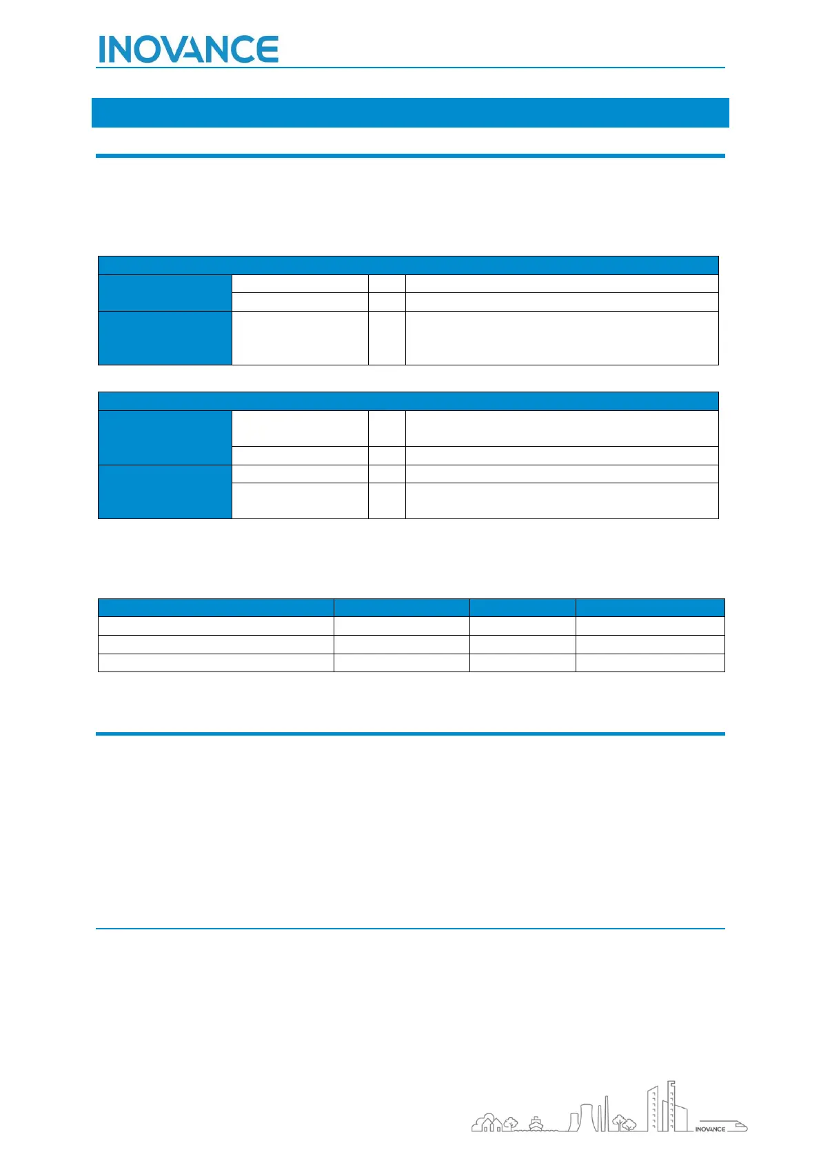
Drive structures its parameters into two main categories: basic function parameters, and monitoring function
parameters. Each category is divided in different groups, and each group contains multiple parameters with a
related functionality.
Rectifier parameters:
Basic function
parameters
F0, F1, F4, F5, F7, FA, FD, FF, FP
Monitoring
function
parameters
Basic function
parameters
F0, F1, F2, F3, F4, F5, F6, F7, F8, F9, FA, FB, FC, FD,
FE, FF, FP
A0, A1, A3, A5, A6, A9, AC, AD, AE, AF
Monitoring
function
parameters
Communication
control parameters
To access to a parameter, you must indicate the group to which it belongs, and the ID of the parameter. See
the sample below:
F0 - Basic Power Supply Unit
AF - Process Data Address Mapping
U0 - Monitoring Parameters
6.2 MEMORY AREAS AND COMMUNICATION ADDRESSES
Drive has RAM and EEPROM memory. All parameters are placed in both areas in the drive: RAM memory, and
EEPROM memory when the drive is power-off.
Parameter communication addresses must be used to perform a read-write and other operations of MD800.
Each parameter has its own EPPROM communication address to be accessed.
Furthermore, in the case of Basic Function Parameters, to avoid an intensive use of the drive’s EEPROM
memory, also they can be accessed to the RAM memory using a particular communication address.
6.2.1 EEPROM MEMORY ACCESS
The communication address to access to the EEPROM memory of the parameter, is represented in hexadecimal
format.
Following the same way as the parameter name, the communication address is made up of two parts:
• The two most significant digits that represent the group to which the parameter belongs
• And the two least significant digits that represent the ID of the parameter

 Loading...


