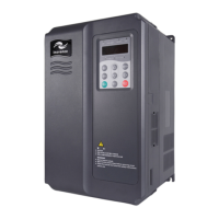
55
INOVANCE TECHNOLOGY EUROPE GmbH
MD800 EtherCAT Starting Guide_EN_v1.1_20211109.docx
In the start-stop control mode of the operation panel,
it is used for running operation.
Stop command /
fault reset
In the running state, it is used to stop the running
operation.
In the fault alarm state, it is used to reset operation.
8.2 INVERTER MODULE LEDS
Table 1 - Description of Inverter Module Indicators
Steady on: The device is in the power-on state.
Off: The device is powered off
Steady on: The device is in operation.
Off: The device is in a stopped state.
Flashing: operated by rectifier keyboard
Steady on: The device is malfunctioning.
Off: The device is normal.
Flashing: The device has an alarm
8.3 RECTIFIER MODULE DISPLAY
Keypad Data Display
• Axis number
Two-digit digital tube display, 0 means rectifier module, 1~8 means inverter module.
• Status display area
Table 2 - Status icon description
Steady on: the device is in torque
control mode
Blinking: the device is in the state of
autotuning
Steady on: The command source is
selected as the terminal control
channel
Blinking: The command source is
selected as the communication control
channel

 Loading...


