EtherCAT Communication
‑112‑
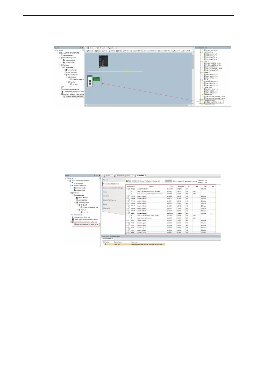
b. Select a device from "Network Devices List" and add it as an AC drive slave
station through drag‑and‑drop.
3. Configure the PDO parameters.
a. Right‑click the arrow position in the figure and add the required TPDO mapping.
The control command of RPDO and inverter state of TPDO can be modified.
RPDO must be configured; otherwise, an error may occur during operation.
Axis#1 Outputs means the control data received by axis 1 from the master
station. Axis#1 Inputs means the state data sent by the axis 1 to the master
station. MD800 can configure up to eight axes. You can select Axis#16 Inputs to
enable the power supply unit to send the state data to the master station.
b. Download the project to the PLC.
Click EtherCAT I/O Mapping, and you can view the TPDO data and RPDO data in
real time.

 Loading...


