CANopen and CANlink Communication
‑41‑
Table 3–5 NodeGuarding return status
Data Bit Description
Bit7
"0" or "1" must be alternatively set every
time.
Bit6 to bit0
State:
4: Stopped
5: Operational
127: Pre‑operational
● Heartbeat packet
The nodes can be configured to periodically generate Heartbeat packets. The
status word bit7 is "0" and bit6 to bit0 are the same as those described in "
Table
3–6 Heartbeat packet
"
on page 41
for NodeGuarding. The Heartbeat time is set in
the standard protocol object 0x1017. One node cannot support both
NodeGuarding and Heartbeat mechanisms.
Table 3–6 Heartbeat packet
COB‑ID RTR Data0
0x700+Node‑ID
0
Status word
3.2 Networking and Interfaces
Communication Networking
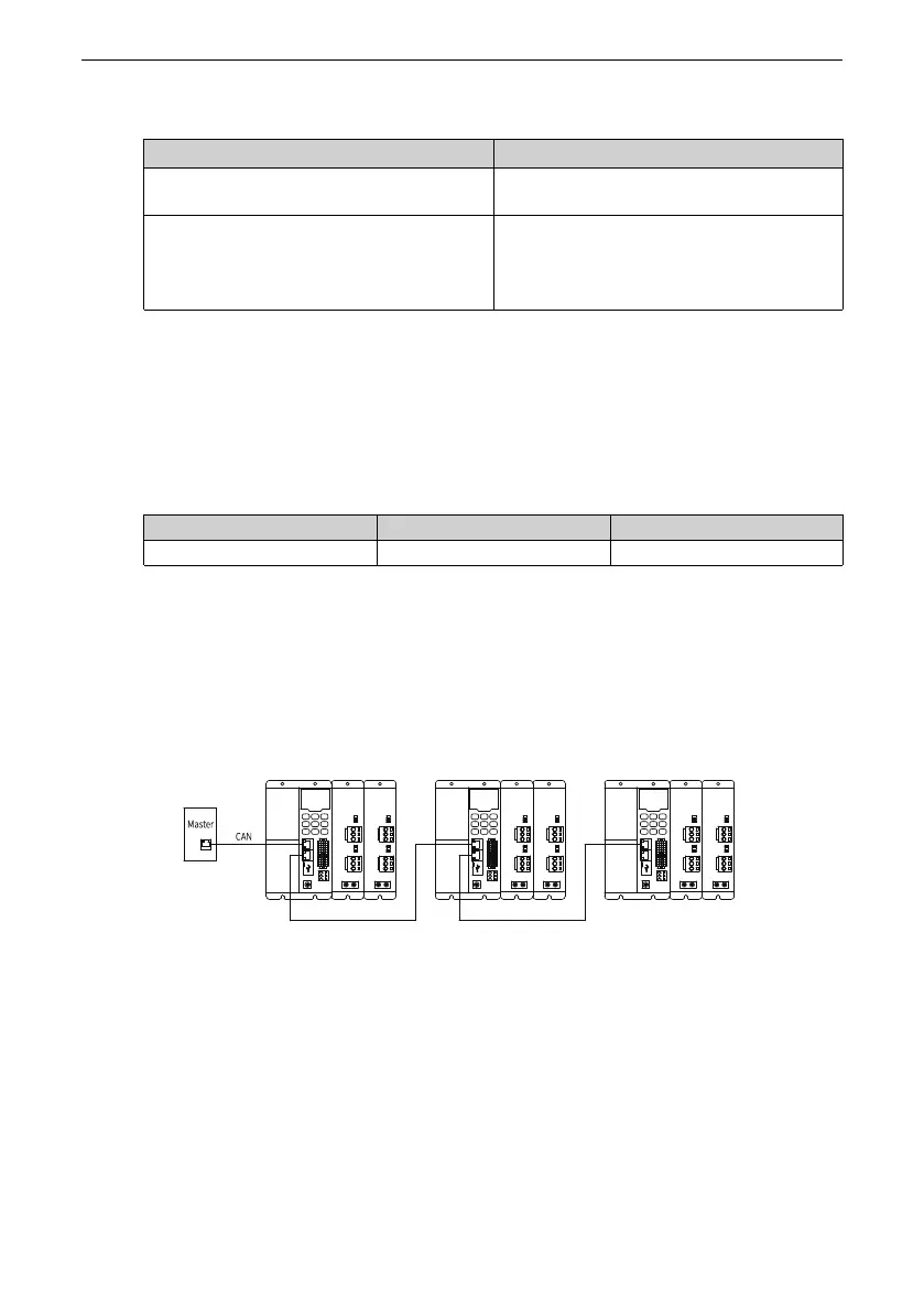
The following figure shows the CAN bus topology. Use shielded twisted pair as the
CAN bus. Two 120 Ω termination resistors must be connected at each end of the bus
to avoid signal reflection. Reliable single‑point grounding is often used for shields.
Figure 3‑3 CAN bus topology
Communication Interface
The CANopen/CANlink communication ports are on the power supply unit and use
dual RJ45 terminals, as shown below.

 Loading...


