Modbus Communication
‑21‑
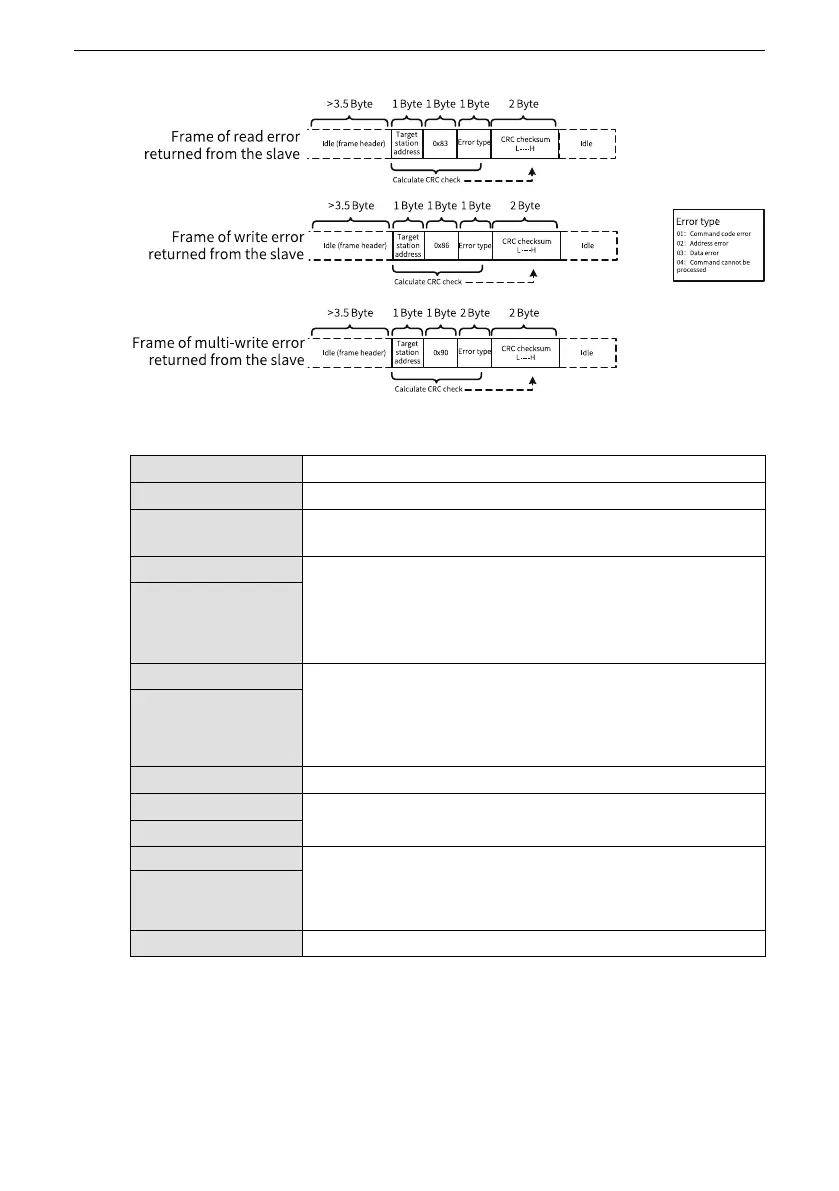
Table 2–3 Data frame fields
Frame header (START)
Idle time greater than 3.5‑byte transmission time
Slave address (ADR)
Communication address range: 1 to 247; 0 = Broadcast
Command code (CMD)
03: Read slave parameters; 06: Write slave parameters; 10: Multi‑
write slave parameters
Parameter address (H) Internal parameter address of the AC drive, expressed in
hexadecimal. Parameters are divided into parameter type and
non‑parameter type (for example, operation status parameters
and operation commands). See the definition of addresses.
Low‑order bytes follow high‑order bytes during transmission.
Parameter address (L)
Parameter count (H) Number of parameters read in this frame. The value 1 indicates
reading one parameter. Low‑order bytes follow high‑order bytes
during transmission.
According to this protocol, only one parameter can be rewritten
at a time without this field.
Parameter count (L)
Data bytes The data length, which is twice the number of parameters
Data (H)
Response data or data to be written. Low‑order bytes follow
high‑order bytes during transmission.
Data (L)
CRC low bit Detection value: CRC16 check value. High‑order bytes follow low‑
order bytes during transmission.
For details of the calculation method, see the description of CRC
in this section.
CRC high bit
END
3.5‑byte transmission time
CRC check:
Cyclical Redundancy Check (CRC) uses the RTU frame format. A Modbus message
includes a CRC‑based error check field. The CRC field is used to check content of the
entire message. The CRC field contains two bytes, making up a 16‑bit binary value.
The CRC field is calculated by the transmitting device, and then added to the

 Loading...


