PROFINET Communication
‑64‑
Ethernet pins. They can be connected using crossover cables or straight‑through
cables.
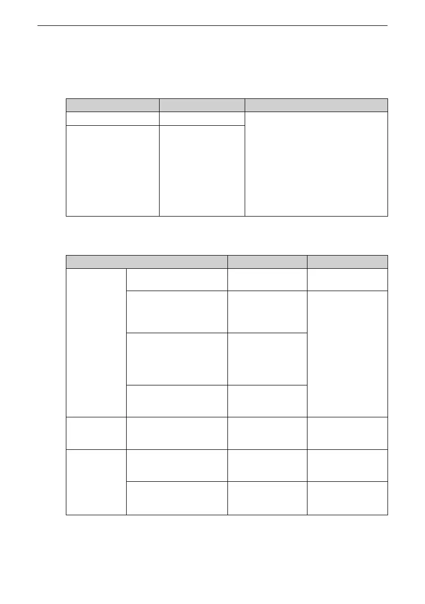
Table 4–1 Description of PN card terminals
Terminal Code Terminal Name
Description
Port1
Network port 1 When the topology is not configured,
any terminal can be connected to the
PLC. When the topology is configured,
port 1 and port 2 must be
distinguished.
After the PN card is installed, face the
RJ45 socket, the port on your left is
port 1 and that on your right is port 2.
For operation stability, use Cat 5e
shielded twisted pair LAN cables.
Port2
Network port 2
Table 4–2 Description of PN card indicator
Indicator
Status Description
Solution
RUN/ERR Steady ON in green The communication
is normal.
None
Steady ON in red The communication
between the PN card
and a node times
out.
1. Restart the PN
card.
2. Remove field
interference.
Flicker quickly in red
(flicker once every 500 ms)
The communication
between the PN card
and the power
supply unit times
out.
Flicker slowly in red (flicker
once every 1s)
The communication
inside the PN card
times out.
PN RUN
Steady ON The PN card
communication is
normal.
None
PN ERR
Steady ON The PN card lost
communication with
the master station.
Check the cable
connection.
Flicker The master station
sends a flicker
request.
None

 Loading...


