EtherCAT Communication
‑97‑
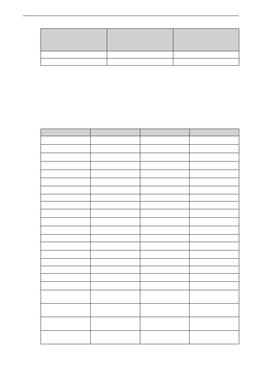
Device Type
Object Dictionary Index
Range of I/O Device
Object Dictionary Index
Range of CANopen402
Protocol
Drive unit axis 7 0x5000 to 0x50FF 0x9000 to 0x97FF
Drive unit axis 8 0x5800 to 0x58FF 0x9800 to 0x9FFF
When an MD800‑ECAT card is used, the written PDO1 and PDO2 are mapped to U3‑17
and U3‑16 respectively by default. Note that the first two items of TxPDO configured
on the master station must be U3‑17 and U3‑16 in sequence.
For multi‑axis AC drives, the mapping must be configured as described above.
Communication Monitoring Parameters of Drive Unit
Table 5–10 Communication monitoring parameters of drive unit
Para. No. Name Unit Decimal Address
U0‑00
Operation frequency
0.01 Hz 28672
U0‑01
Frequency reference
0.01 Hz 28673
U0‑02
Bus voltage
0.1 V 28674
U0‑03
Output voltage
1 V 28675
U0‑04
Output current
0.1 A 28676
U0‑05
Output power
0.1 kW
28677
U0‑06
Output torque
0.1% 28678
U0‑07 DI state 1 28679
U0‑08
DO/RO state
1 28680
U0‑09
AI1 voltage
0.01 V 28681
U0‑10
AI2 voltage
0.01 V 28682
U0‑11
AI3 voltage
0.01 V 28683
U0‑12
Count value
1 28684
U0‑13
Length value
1 28685
U0‑14
Load speed display
1 28686
U0‑15
PID reference
1 28687
U0‑16
PID feedback
1 28688
U0‑17
PLC stage
1 28689
U0‑19
Feedback speed
0.01 Hz 28691
U0‑20
Remaining running
time
0.1 min 28692
U0‑21
Voltage after AI1 gain
and offset
0.001 V 28693
U0‑22
Voltage after AI2 gain
and offset
0.001 V 28694
U0‑23
Voltage after AI3 gain
and offset
0.001 V 28695

 Loading...


