- 46 -
3 Wiring
3
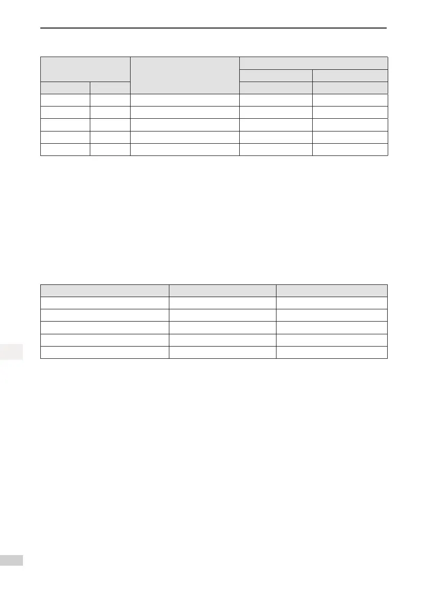
Table 3-9 9-pin connection relation of 20-bit encoder cables of SV820N series
DB9 on Servo Drive Side
Function Description
9 PIN
Motor Side
20-29 Aviation Plug
Signal Pin No. Pin No. Pin No.
PS+ 5 Serialcommunicationsignal+ 3 A
PS- 6 Serial communication signal - 6 B
+5V 1 Encoder+5Vpowersupply 9 G
GND 2 Encoder+5Vpowerground 8 H
PE Housing Shield 7 J
Observethefollowingprecautionswhenwiringtheencoder:
Correctly ground the servo drive and shield of the servo motor. Otherwise, the servo drive will report a false
alarm.
Do not connect cables to the "Reserved" terminals.
To determine the length of the encoder cable, consider the voltage drop caused by the cable resistance and
signal attenuation caused by the distributed capacitance. It is recommended to use a twisted-pair cable of
size 26 AWG or above (as per UL2464 standard) which is 10 m long or shorter.
It is recommended that the 22–26 AWG cables and matching AMP170359-1 terminals be used for the 10B,
20B, 40B, and 75B series motors. If longer cables are required, cables of a larger diameter should be used,
as described in the following table.
Table 3-10 Recommended cables
Diameter Ω/km Allowable Length (m)
26 AWG (0.13 mm
2
) 143 10.0
25 AWG (0.15 mm
2
) 89.4 16.0
24 AWG (0.21 mm
2
) 79.6 18.0
23 AWG (0.26 mm
2
) 68.5 20.9
22 AWG (0.32 mm
2
) 54.3 26.4
If the cables of above 22 AWG are required, contact Inovance’s sales personnel.

 Loading...


