47
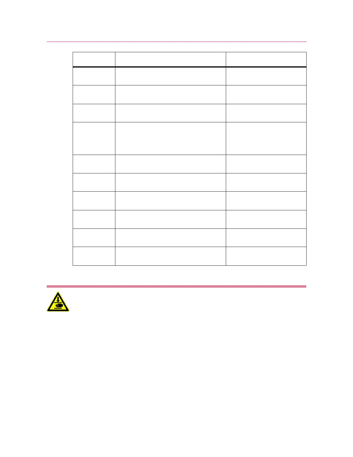
System components
Product Support: www.instron.com
Do not connect the two exhaust ports together.
In some situations, unexpected grip motion can result. To prevent this, do not link the
exhaust ports (for example with a “T” or “Y” fitting). The two exhaust ports must remain
separate.
9 Pneumatic grips - air exhaust connector Install air muffler or connect
to exhaust system
10 Pneumatic grips - air exhaust connector Install air muffler or connect
to exhaust system
11 Power inlet connection, power switch,
fuses and voltage selector
“Power supply
compatibility” on page 39
12 Ground connection Connect to the ground stud on
the rear of the load frame
using the ground connection
cable supplied
1 Motor feedback (encoder) connection Matching connection 1 shown
in Figure 7, Figure 8
3 Connection for limit rod stop, speed sensor
and emergency stop
Matching connection 3 shown
in Figure 7, Figure 8
4 Connection for Indicator panel Matching connection 4 shown
in Figure 7, Figure 8
13 Ethernet (to Bluehill
®
Operator Dashboard)
or separate computer
5 Connection for motor power Matching connection 5 shown
in Figure 7, Figure 8
2 Connection for handset Matching connection 2 shown
in Figure 7, Figure 8
Label Component More detail