Chapter 3: Additional System Details
40 M47-17028-EN
that the oil is to the top of the sight gauge when the hydraulic cylinder is completely retracted. Filling the
reservoir with the hydraulic cylinder slightly extended will cause overflowing of the reservoir when the
hydraulic cylinder is retracted. The maximum temperature of the hydraulic oil under normal operating
conditions should remain below 60 deg. C (140 deg. F), and should never exceed 80 deg. C (176 deg. F).
Consult factory for operating conditions that result in oil temperatures that exceed 80 deg. C (176 deg. F).
Oil temperature is monitored by a temperature switch inside the reservoir, see “Oil temperature
switch” on page 41.
Air breather assembly
An air breather assembly (2, Figure 17) is placed on the reservoir’s fill hole to allow the reservoir to
breathe while preventing dirt from entering the reservoir. It can be easily removed for access to the
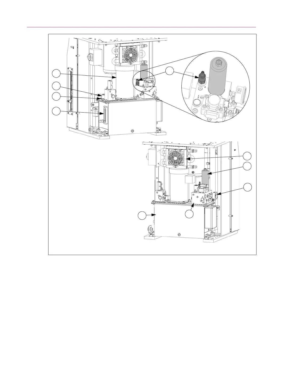
Figure 17. Components of the HPS.
Rear and side covers removed.
1. Motor
2. Air breather filter
3. Fill hole
4. Sight gauge
5. Oil filter
6. Heat exchanger and fan
7. System pressure gauge
8. Relief valve RV1
9. Servo manifold
10. Reservoir
1
2
4
10
9
7
6
5
3
8
 Loading...


