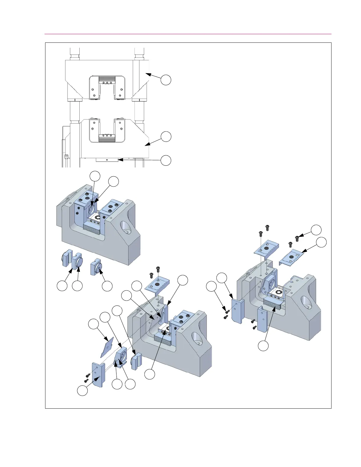
Figure 11. Components of the grip assemblies for G7-style crossheads.
1. Tension crosshead
2. Adjustable crosshead
3. Bumper plate
4. Grip jaw
a. Locating boss
b. Retainer button (600DX only)
5. Jaw carrier
a. Jaw carrier recess
6. Guide plate (front and rear)
7. Socket head cap screw and washer
(see Table 12 for size, quantity and torque)
8. Piston dust cover
9. Grip dust cover
10. Button head cap screw
(see Table 12 for size and quantity)
11. Wear plate
12. Guide pin (one on each side of jaw carrier)
13. Retainer setscrew (M8) (600DX only)
14. Access hole for retainer setscrew (600DX only)
15. Grip pocket
16. Guide slot for guide pin
17. Push plate and piston
View A
View B
View C
1
2
3
5
5a
4b
4a4
4
15
16
6
5
11
14
12 13
17
8
7
6
10
9