Chapter 3: Operation
54 M47-17027-EN
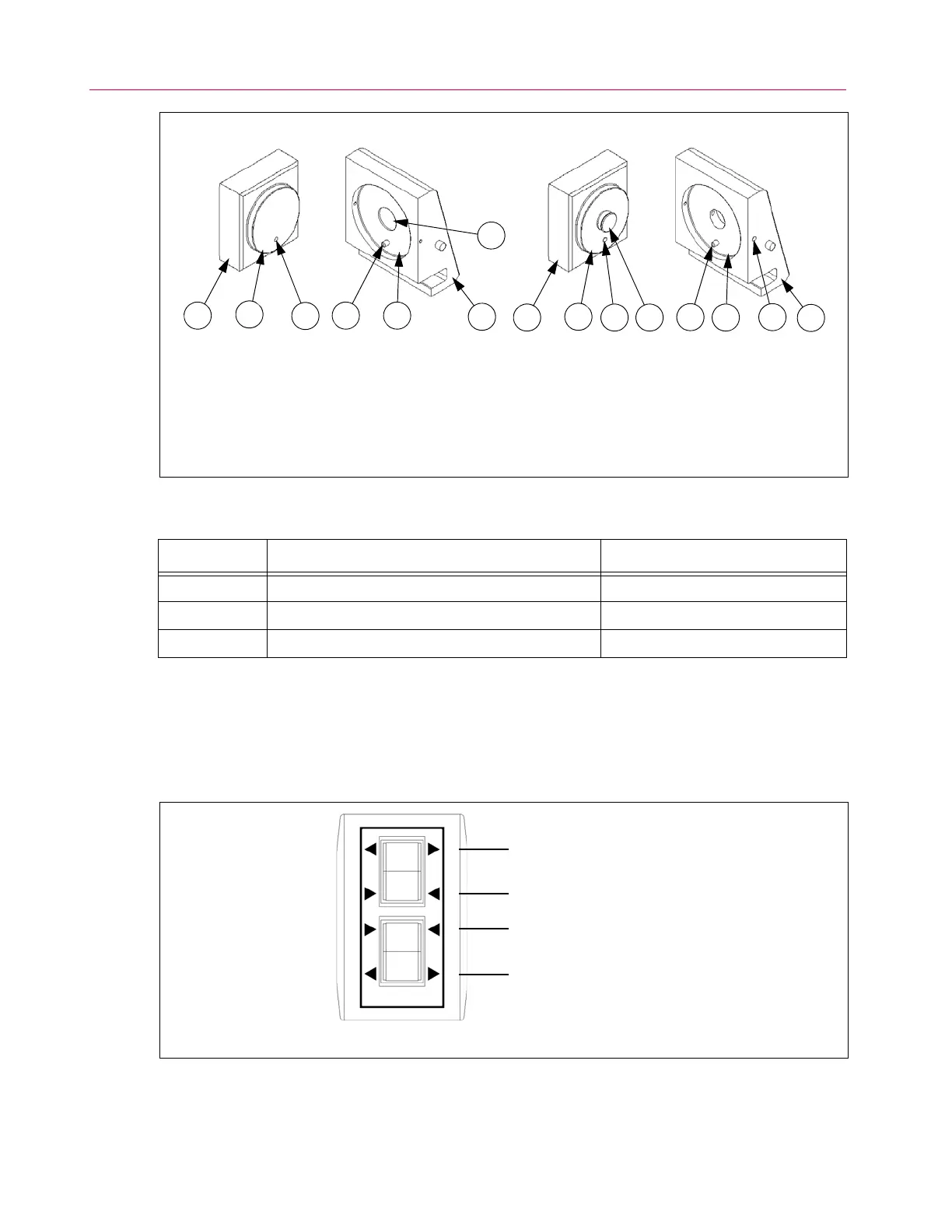
Figure 12. Details of grip jaw and jaw carrier.
Table 13. Function of grip controls (see Figure 13 on page 54.
Function Switch Type Use
Open Momentary - returns to Neutral when released Unclamp grip jaws
Close
1
Latch - remains at Close when released Clamp grip jaws, test in progress
Neutral N/A (no switch activated) No test in progress, system idle
1. If a switch is in the Close position and main power is lost to the frame*, the grips will stop and hold their current
position; also the switch will remain latched in the Close position but will be put into Neutral mode (i.e. will not
function). When power is restored to the frame, the grips and the grip controls will remain in this hold/neutral
condition until the switch is reset. The switch must be reset to restore grip function. To reset the switch, move it to
the Neutral position and then operate as desired.
* For conditions that result in loss of main power to the frame, see “Loss of power” on page 60.
Figure 13. Hydraulic grip control handset.
1. Grip jaw
2. Locating boss
3. Alignment hole
4. Alignment pin
5. Jaw carrier recess
6. Jaw carrier
7. M agn et ( 300 DX o nly )
8. Retainer button (600DX only)
9. Retainer setscrew (M8) (600DX only)
300DX Frames 600DX Frames
1
2
3
4 5
6
1
7
2
3 8
4
5
9
6
Upper open
Upper close
Lower close
Lower open
 Loading...


