CombiLock 200 simplex / pro / RFID
Handbuch V. 1.05 77 Manual V.1.05
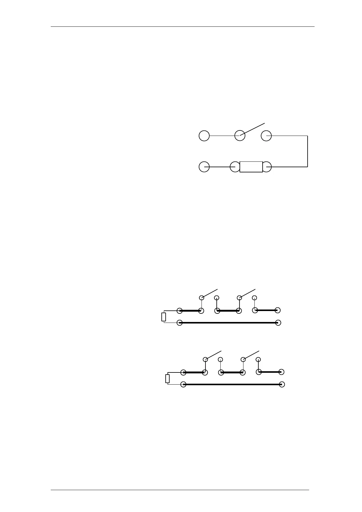
Anti-Tamper Circuit
CombiXT features an anti-tamper circuit implemented as a cover contact. You can add
elements to the anti-tamper circuit. If no further anti-tamper elements are to be
included, plug the jumper J3 next to the cover contact. You may solder on a resistor for
monitoring the anti-tamper circuit as a replacement for the jumper.
In standby mode / idle state, the anti-tamper circuit is closed.
Solder Connection Block
for boltwork- and door contacts
Optionally 2 boltwork – and 2 door contacts can be applied at the blocking device. You
can apply resistors at the contacts in order to have the contacts monitored. Solder the
wires on at the solder points.
Example of contact connection:
Solder point 1:
Solder point 2:
Note:
Via the solder connection block you can connect these contacts to the burglar alarm
system. Apart from providing that option, the solder connection block does not have
any functional relevance for the lock / system.
Cover contact
Resistance monitoring
(optional)
Terminal 1
Terminal 2
Connection for Anti-Tamper Circuit
J3
Door contact 1 Door contact 2
Resistance
Connection to
BAS
Boltwork
contact 1
Boltwork
contact 2
Resistance
Connection
to BAS