101
Zone 2—Continued
The 12V triggers A, B, and C can be used to turn on 12V trig-
ger-capable components automatically when they are selected
as the input source. The triggers can be set so that they activate
when a connected component is selected as the input source for
the main room, Zone 2 or any combination of rooms.
When triggered, the output from a 12V TRIGGER OUT
goes high (+12 volts and 125 milliamperes max. at
TRIGGER OUT A; +12 volts and 25 milliamperes max.
at TRIGGER OUT B and C).
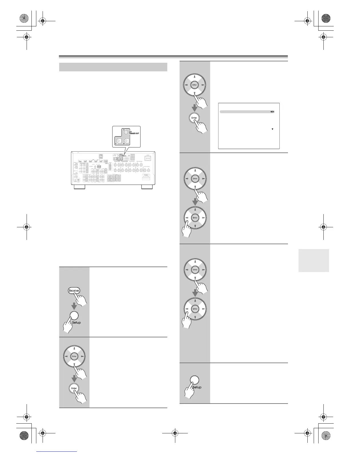
Hookup
• Use a miniplug cable to connect the AV receiver’s 12V
TRIGGER OUT A, B, or C jack to the 12 V trigger
input on a connected component.
When several components are turned on simultaneously by
using triggers A, B, and C, depending on the type of com-
ponents, a large amount of current may be drawn momen-
tarily. To prevent this, you can delay trigger signals A, B,
and C individually. Another application for trigger delay is
eliminating the “thump” noise that’s sometimes heard when
a source component is turned on. Delaying the trigger sig-
nal for your power amplifier so that it’s the last component
to be turned on will accomplish this.
Using the 12V Triggers
1
Remote
controller
Press the [Receiver] button, fol-
lowed by the [Setup] button.
The main menu appears onscreen.
2
Use the Up and Down [q]/[w] but-
tons to select “6. Miscella-
neous”, and then press [Enter].
The Miscellaneous menu appears.
3
Use the Up and Down [q]/[w] but-
tons to select “12V Trigger A, B,
or C Setup”, and then press
[Enter].
The 12V Trigger A, B, or C Setup
screen appears.
4
Use the Up and Down [q]/[w] but-
tons to select “Delay”, and use
the Left and Right [e]/[r] but-
tons to select: 0sec, 1sec, 2sec,
or 3sec.
When 0 sec is selected, the trigger sig-
nal is output as soon as the input source
is changed.
5
Use the Up and Down [q]/[w] but-
tons to select an input source,
and use the Left and Right [e]/
[r] buttons to select an option.
Off: No trigger signal is output.
A 12-volt trigger signal is output when
the connected component is selected as
the source for:
Main: Main room.
Zone2: Zone 2.
Main/Zone2:
Main room or Zone 2.
Note:
By default, all input sources on the
“12V Trigger A Setup” menu are set to
“Main”, those on the “12V Trigger B
Setup” menu are set to “Zone 2”, and
those on the “12V Trigger C Setup”
menu are set to “Off”.
6
When you’ve finished, press the
[Setup] button.
The setup menu closes.
6–3. 12V Trigger A Setup
Delay
DVD/BD
VCR/DVR
CBL/SAT
GAME
AUX
0sec
Main
Main
Main
Main
Main
DTR-30.1_En_A.book 101 ページ 2009年4月21日 火曜日 午後5時51分