98
Zone 2
—Continued
The 12V triggers A, B, and C can be used to turn on 12V
trigger-capable components automatically when they are
selected as the input source. The triggers can be set so
that they activate when a connected component is
selected as the input source for the main room or Zone 2.
When triggered, the output from a 12V TRIGGER OUT
goes high (+12 volts, 100 milliamperes max).
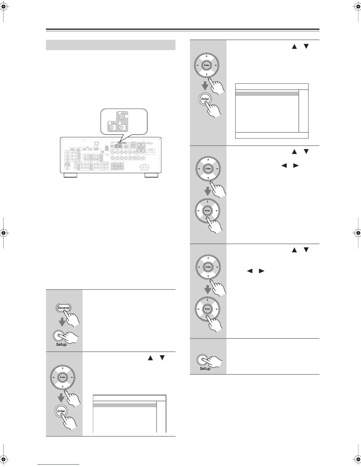
Hookup
• Use a miniplug cable to connect the AV receiver’s 12V
TRIGGER OUT A, B, or C jack to the 12 V trigger
input on a connected component.
When several components are turned on simultaneously
by using triggers A, B, and C, depending on the type of
components, a large amount of current may be drawn
momentarily. To prevent this, you can delay trigger sig-
nals A, B, and C individually. Another application for
trigger delay is eliminating the “thump” noise that’s
sometimes heard when a source component is turned on.
Delaying the trigger signal for your power amplifier so
that it’s the last component to be turned on will accom-
plish this.
Using the 12V Triggers
1
Press the [Receiver] Remote
Mode button, followed by the
[Setup] button.
The main menu appears onscreen.
2
Use the Up and Down [ ]/[ ]
buttons to select
“6. Miscellaneous,” and then
press [Enter].
The Miscellaneous menu appears.
ANTENNA
FM
AM
75
SIRIUS
CB
12V TRIGGER OUT
A
6. Miscellaneous
1.Volume Setup
2.OSD Setup
3.12V Trigger A Setup
4.12V Trigger B Setup
5.12V Trigger C Setup
3
Use the Up and Down [ ]/[ ]
buttons to select “12V Trigger A,
B, or C,” and then press [Enter].
The 12V Trigger A/B/C Setup screen
appears.
4
Use the Up and Down [ ]/[ ]
buttons to select “Delay,” and use
the Left and Right [ ]/[ ] but-
tons to select: 0 sec, 1 sec, 2 sec,
or 3 sec.
When 0 sec is selected, the trigger sig-
nal is output as soon as the input source
is changed.
5
Use the Up and Down [ ]/[ ]
buttons to select an input
source, and use the Left and
Right [ ]/[ ] buttons to select
an option.
Off:
No trigger signal is output.
A 12-volt trigger signal is output when
the connected component is selected as
the source for:
Main:
Main room.
Zone2:
Zone 2.
Main/Z2:
Main room or Zone 2.
6
When you’ve finished, press the
[Setup] button.
Setup closes.
6-x. 12V Trigger x Setup
Delay 1sec
DVD Main/Zone2
VCR/DVR Main/Zone2
CBL/SAT Main/Zone2
GAME/TV Main/Zone2
AUX Main/Zone2
TAPE Main/Zone2
CD Main/Zone2
DTR-5.9En.book Page 98 Tuesday, April 15, 2008 9:53 AM