125
Zone 2 and Zone 3
—Continued
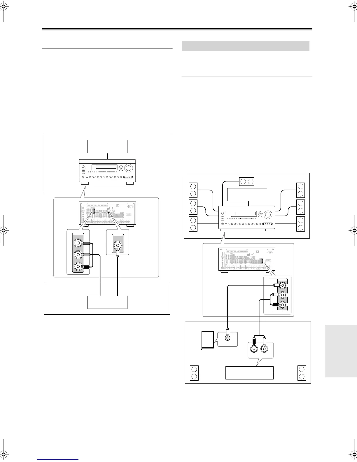
Zone 2 Video Outputs
The AV receiver features a composite video output and
component video output for connection to a TV in Zone 2,
so you can enjoy both audio and video in that zone.
Hookup
• Use a composite video cable to connect the AV
receiver’s ZONE 2 OUT V jack to a composite video
input on your Zone 2 TV.
• Alternatively, use a component video cable to connect
the AV receiver’s COMPONENT VIDEO MONITOR
OUT 2/ZONE 2 OUT jacks to a component video input
on your Zone 2 TV.
• If you use the COMPONENT VIDEO MONITOR
OUT 2/ZONE 2 OUT, you must set the Monitor Out2
setting to Zone 2 (see page 48).
Notes:
• The ZONE 2 OUT V jack outputs video from compo-
nents connected to composite video inputs and S-Video
inputs.
• The COMPONENT VIDEO MONITOR
OUT 2/ZONE 2 OUT outputs video from components
connected to component video inputs.
Zone 3 speakers must be connected to an amp in Zone 3.
Connecting Your Zone 3 Speakers
You can enjoy 2-channel stereo playback in Zone 3 and a
different source to those selected for your main room and
Zone 2.
Hookup
• Use an RCA audio cable to connect the AV receiver’s
ZONE 3 PRE OUT L/R jacks to an analog audio input
on your Zone 3 amp.
• Use an RCA audio cable to connect the AV receiver’s
ZONE 3 PRE OUT SW jack to the line input on a pow-
ered subwoofer in Zone 3.
• Connect your Zone 3 speakers to the speaker terminals
on your Zone 3 amp.
Note:
•With the default settings, the Zone 3 volume must be
set on the Zone 3 amp. If your Zone 3 amp has no vol-
ume control, set the Zone 3 Out setting to Variable so
that you can set the Zone 3 volume on the AV receiver
(see page 127).
FRONT L
(BTL)
FRONT R
(BTL)
V
S
MONITOR
OUT
ZONE 2
OUT
RS232
DIGITAL
COAXIAL
OPTICAL
REMOTE
CONTROL
IN 1
IN 1
IN 2
IN IN IN IN
PHONO
ZONE2 L
FRONT R FRONT LSURR R CENTER SURR L
SURR BACK R
CD TAPE AUX 1
GAME/TV
GAME/TV CBL/SAT
CBL/SAT
AUX 1 VCR/DVR
VCR/DVR DVD
DVD
GND
IN 2
IN 3
LL
RR
ASSIGNABLE
(DVD)
(CBL/SAT)
(VCR/DVR)
(GAME/TV)
(CD)
OUT
OUT
IN IN
OUT
IN IN FRONT FRONTCENTER
SUBWOOFER SUBWOOFER
CENTERSURR SURR
MULTI CH
PRE OUT
SURR BACK SURR BACK
AC INLET
Bi-AMP
SURR BACK L
Bi-AMP
ETHERNET
HDMI
IN 1IN 2IN 3IN 4
ASSIGNABLE
OUT
MAIN
OUT
SUB
ZONE2 R
AM
ANTENNA
FM75
COMPONENT VIDEO
ASSIGNABLE
IN 3
Y
C
B
/P
B
C
R
/P
R
IN 2 IN
1(DVD)
MONITOR
OUT 1
MONITOR OUT 2
/ZONE 2 OUT
V
S
ZONE 2 ZONE 3
PRE OUT
L
R
SW
AB
IR
12V TRIGGER OUT
B
OUT
C
ZONE 2
OUT
MONITOR OUT 2
/ZONE 2 OUT
Main room
TV
Zone 2
AV receiver
TV
or
Connecting Zone 3
FRONT L
(BTL)
FRONT R
(BTL)
V
S
MONITOR
OUT
ZONE 2
OUT
RS232
DIGITAL
COAXIAL
OPTICAL
REMOTE
CONTROL
IN 1
IN 1
IN 2
IN IN IN IN
PHONO
ZONE2 L
FRONT R FRONT LSURR R CENTER SURR L
SURR BACK R
CD TAPE AUX 1
GAME/TV
GAME/TV CBL/SAT
CBL/SAT
AUX 1 VCR/DVR
VCR/DVR DVD
DVD
GND
IN 2
IN 3
LL
RR
ASSIGNABLE
(DVD)
(CBL/SAT)
(VCR/DVR)
(GAME/TV)
(CD)
OUT
OUT
IN IN
OUT
IN IN FRONT FRONTCENTER
SUBWOOFER SUBWOOFER
CENTERSURR SURR
MULTI CH
PRE OUT
SURR BACK SURR BACK
AC INLET
Bi-AMP
SURR BACK L
Bi-AMP
ETHERNET
HDMI
IN 1IN 2IN 3IN 4
ASSIGNABLE
OUT
MAIN
OUT
SUB
ZONE2 R
AM
ANTENNA
FM75
COMPONENT VIDEO
ASSIGNABLE
IN 3
Y
C
B
/P
B
C
R
/P
R
IN 2 IN
1(DVD)
MONITOR
OUT 1
MONITOR OUT 2
/ZONE 2 OUT
V
S
ZONE 2 ZONE 3
PRE OUT
L
R
SW
AB
IR
12V TRIGGER OUT
B
OUT
C
R
L
IN
LINE INPUT
ZONE 3
PRE OUT
L
R
SW
Main room
Zone 3
Receiver/
integrated amp
AV receiver
Powered
subwoofer
TV
DTR-8.8En.book Page 125 Friday, February 15, 2008 1:17 PM