1000BASE-T/100BASE-TX/10BASE-T Physical Layer Compliance Tests Manual
Intel Confidential 17
1000BASE-T Maximum Output Droop
6. Adjust the oscilloscope to the settings for Points H and J as shown below.
NOTE: Points F and G are like H and J, except they are negative polarity.
7. Measure the output voltage with a differential probe connected across the 100-ohm test load
for each channel.
8. Compute the ratios as shown in the example below.
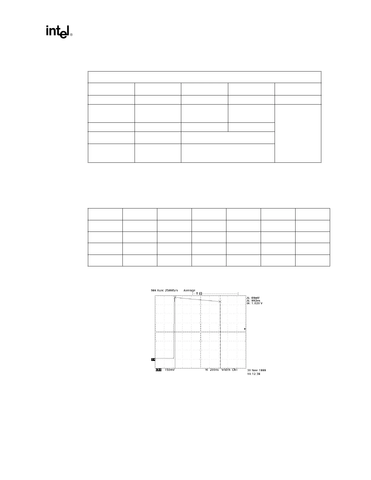
Point H peak = 1.020 Volts:
Figure 3-2. Example Maximum Output Droop Measurement, Point H
Point H and J: Pulse Droop
Trigger Settings Trigger Type Polarity Limits Level
Pulse width Positive 7 ns to 9 ns +500 mV
Scaling Vertical Scale
Vertical
Position
Horizontal
Scale
150 mV / division -3.0 division 200 ns / division
Cursors Display Mode Acquisition Mode
Horizontal bars for
H; Crosshairs for H
and J
Vectors Average on
Channel Point F Point G Ratio Point H Point J Ratio
A -1.024 -0.982 95.898% 1.020 0.984 96.471%
B -1.022 -0.985 96.380% 1.022 0.985 96.380%
C -1.019 -0.985 96.663% 1.018 0.985 96.853%
D -1.019 -0.982 96.369% 1.012 0.983 97.134%