1000BASE-T MDI Common-Mode Output
1000BASE-T/100BASE-TX/10BASE-T Physical Layer Compliance Tests Manual
28 Intel Confidential
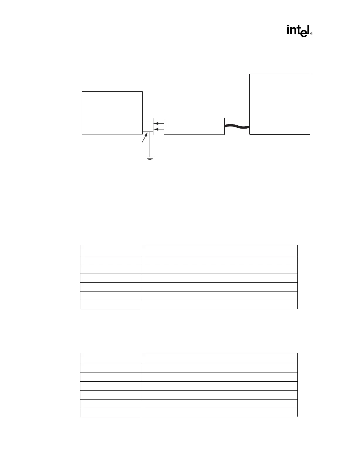
ensure that the ground on test fixture 40-32 is connected to a stable (not floating) ground
through the RJ-45 of the UUT. See Appendix A for more details.
2. Adjust the probe settings to:
— DC reject = on
— Bandwidth = full
— Attenuation = set to divide by one
3. Select the Common-Mode Output: 40.8.3.3 Test on the UUT from the 1000BASE-T PHY
Configuration Tests menu in gigconf.exe.
4. Set the scope settings for positive common-mode measurement.
5. Adjust trigger level, in the positive direction, until trigger is lost and place cursor on the
maximum or peak voltage.
6. Record maximum or peak amplitude value(s).
7. Set scope settings for negative common-mode measurement.
Differential Probe
w/ 1 GHz BW
Unit Under Test
(UUT)
Digitizing
Oscilloscope
Test Fixture 40-32
100 Ohm Resistive Load
RX
RJ-45
TX
To Chassis
GND (can be metal shield on RJ-45)
Scope Parameter Setting
Horizontal Scale 2 ns / division
Vertical Range -25 mV to +25 mV (at 10 vertical divisions, this equals 5 mV / division
Trigger Type Level and positive or negative edge
Trigger Level Adjust from 0 V to +25 mV to find peak voltage
Trigger Mode Normal
Display Persistence Infinite persistence or vectors (in other words, dots connected)
Scope Parameter Setting
Horizontal Scale 2 ns / division
Vertical Range -25 mV to +25 mV (at 10 vertical divisions, this equals 5 mV / division
Trigger Type Level and positive or negative edge
Trigger Level Adjust from 0 V to -25 mV to find peak voltage
Trigger Mode Normal
Display Persistence Infinite persistence or vectors (in other words, dots connected)