Intel
®
Celeron
®
D Processor in the 775-Land LGA Package Thermal Design Guide51
Order #303730
Case Temperature Reference Methodology
D.15 Thermocouple Attach Procedure
D.15.1 Thermocouple Conditioning and Preparation
1. Use a calibrated thermocouple as specified in Section D.12 and Section D.13.
2. Measure the thermocouple resistance by holding both wires on one probe and the tip of the
thermocouple to the other probe of the DMM. The measurement should be about~75 ohms for
40-gauge type T thermocouple.
3. Straighten the wire for about 38 mm [1½ inch] from the bead to place it inside the channel.
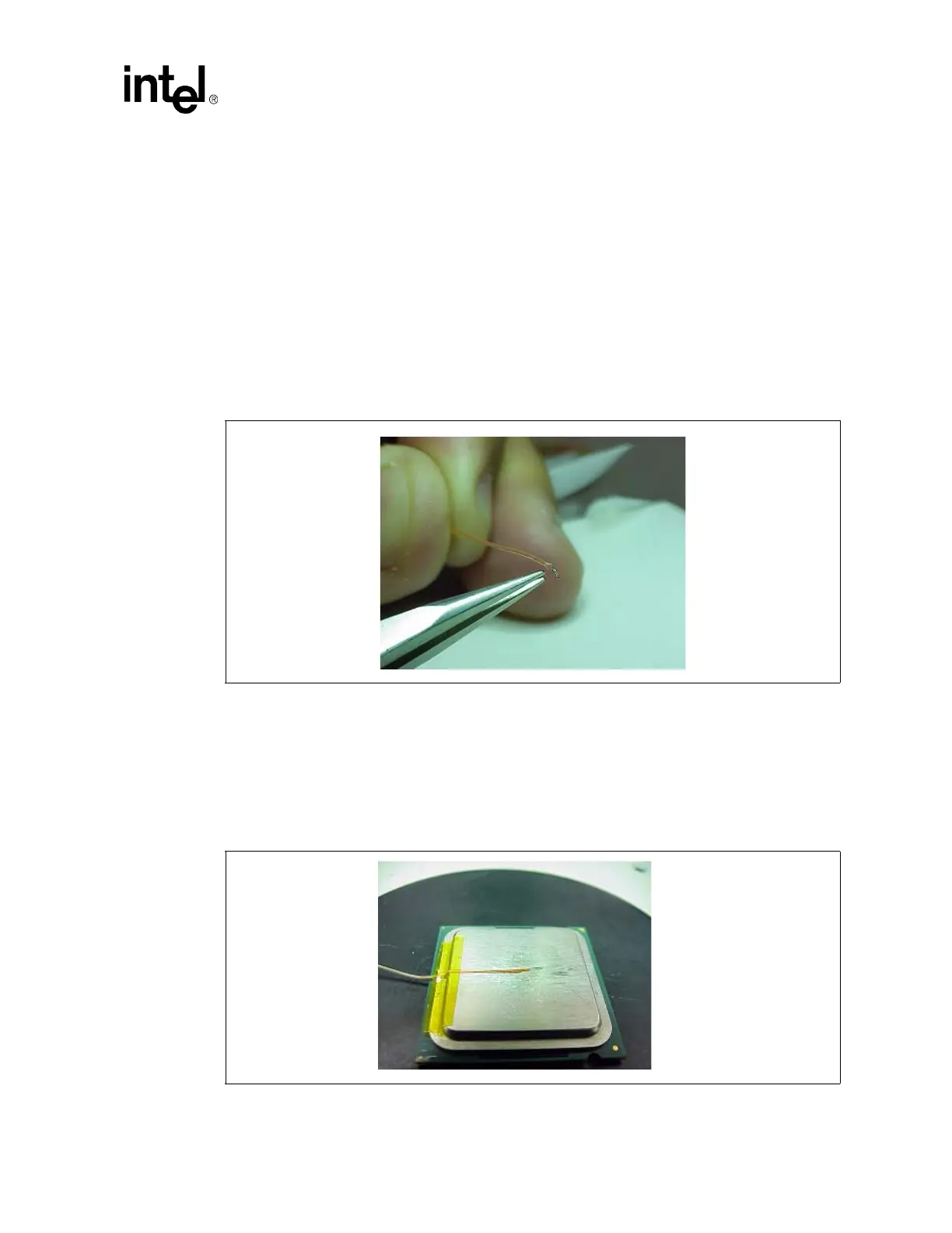
4. Bend the tip of the thermocouple at approximately 45 degree angle by about 0.8 mm [.030
inch] from the tip (Figure 22).
D.15.2 Thermocouple Attachment to the IHS
5. Clean groove with IPA and a lint free cloth removing all residues prior to thermocouple
attachment.
6. Place the thermocouple wire inside the groove; letting the exposed wire and bead extend about
3.2 mm [.125 inch] past the end of groove. Secure it with Kapton* tape (Figure 23).
Figure 22. Bending the Tip of the Thermocouple
Figure 23. Securing Thermocouple Wires with Kapton* Tape Prior to Attach