Technical Reference
45
2.1.2 Memory Map
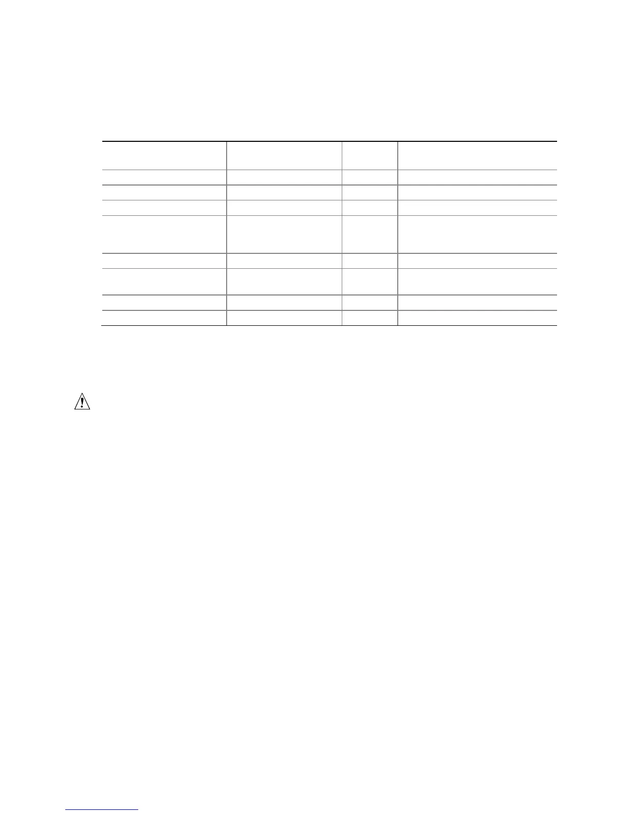
Table 11 lists the system memory map.
Table 12. System Memory Map
Address Range
(decimal)
Address Range
(hex)
Size
Description
1024 K - 4194304 K 100000 - FFFFFFFF 4095 MB Extended memory
960 K - 1024 K F0000 - FFFFF 64 KB Runtime BIOS
896 K - 960 K E0000 - EFFFF 64 KB Reserved
800 K - 896 K C8000 - DFFFF 96 KB Potential available high DOS
memory (open to the PCI bus).
Dependent on video adapter used.
640 K - 800 K A0000 - C7FFF 160 KB Video memory and BIOS
639 K - 640 K 9FC00 - 9FFFF 1 KB Extended BIOS data (movable by
memory manager software)
512 K - 639 K 80000 - 9FBFF 127 KB Extended conventional memory
0 K - 512 K 00000 - 7FFFF 512 KB Conventional memory
2.2 Connectors and Headers
CAUTION
Only the following connectors and headers have overcurrent protection: back panel
and front panel USB.
The other internal connectors and headers are not overcurrent protected and should
connect only to devices inside the computer’s chassis, such as fans and internal
peripherals. Do not use these connectors or headers to power devices external to the
computer’s chassis. A fault in the load presented by the external devices could cause
damage to the computer, the power cable, and the external devices themselves.
Furthermore, improper connection of USB header single wire connectors may
eventually overload the overcurrent protection and cause damage to the board.
This section describes the board’s connectors and headers. The connectors and
headers can be divided into these groups:
• Back panel I/O connectors
• On-board I/O connectors and headers (see page 47 and page 49)