Intel Desktop Board DN2800MT Technical Product Specification
60
2.2.3.4.2 Reset Switch Header
Pins 5 and 7 can be connected to a momentary single pole, single throw (SPST) type
switch that is normally open. When the switch is closed, the board resets and runs the
POST.
2.2.3.4.3 Power/Sleep LED Header
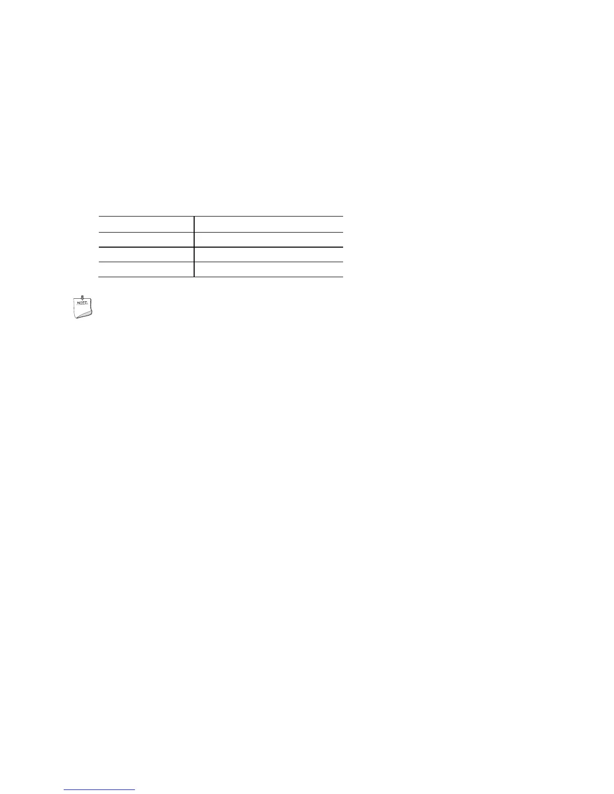
Pins 2 and 4 can be connected to a one- or two-color LED. Table 35 shows the
possible LED states.
Table 36. States for a One-Color Power LED
LED State Description
Off Power off
Blinking Standby
Steady Normal operation
NOTE
The LED behavior shown in Table 35 is default – other patterns may be set via BIOS
setup.
2.2.3.4.4 Power Switch Header
Pins 6 and 8 can be connected to a front panel momentary-contact power switch. The
switch must pull the SW_ON# pin to ground for at least 50 ms to signal the switch on
or off. (The time requirement is due to internal debounce circuitry on the board.) At
least two seconds must pass before the board will recognize another on/off signal.