Technical Reference
59
For information about Refer to
Power supply considerations Section 2.6.1, page 69
2.2.3.4 Front Panel Header
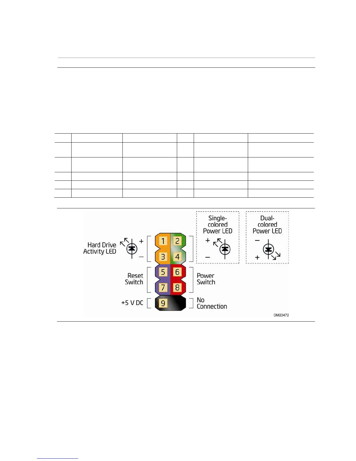
This section describes the functions of the front panel header. Table 34 lists the signal
names of the front panel header. Figure 15 is a connection diagram for the front panel
header.
Table 35. Front Panel Header
Pin Signal Name Description Pin Signal Name Description
1 HDD_POWER_LED Pull-up resistor (750
) to +5V
2 POWER_LED_MAIN [Out] Front panel LED
(main color)
3 HDD_LED# [Out] Hard disk
activity LED
4 POWER_LED_ALT [Out] Front panel LED
(alt color)
5 GROUND Ground 6 POWER_SWITCH# [In] Power switch
7 RESET_SWITCH# [In] Reset switch 8 GROUND Ground
9 +5V_DC Power 10 Key No pin
Figure 15. Connection Diagram for Front Panel Header
2.2.3.4.1 Hard Drive Activity LED Header
Pins 1 and 3 can be connected to an LED to provide a visual indicator that data is
being read from or written to a hard drive. Proper LED function requires a SATA hard
drive or optical drive connected to an onboard SATA connector.