EasyManuals Logo
Home>Intel>Server Board>S1200SPL

Intel S1200SPL User Manual

Intel S1200SPL
147 pages
To Next Page IconTo Next Page
To Previous Page IconTo Previous Page
Page #85 background imageLoading...
Page #85 background image
Intel® Server Board S1200SP Family Technical Product Specification
71
Connector
Quantity
Reference Designators
Connector Type
Pin Count
IPMB
1
J1G2
Header
4
Configuration jumpers
5
J4B1 (Force Integrated BMC update),
J1F4 (Password Clear),
J7B1 (BIOS Recovery),
J4C1 (Reset BIOS Configuration)
J1F1 (ME Firmware Update)
Jumper
3
TPM
1
J8K1
Connector
14
Chassis Intrusion
1
J9B2
Header
2
I/O Module Connector
1
J1C1
Connector
80
SAS Module Connector
1
J4J1
Connector
80
8.2 Power Connectors
The main power supply connection uses an SSI-compliant 2x12 pin connector (J9H1).
Two additional power-related connectors also exist:
One SSI-compliant 2x4 pin power connector (J9B1) to provide 12-V power to the CPU voltage regulators
and memory.
One SSI-compliant 1x5 pin connector (J9F1) to provide I2C monitoring of the power supply.
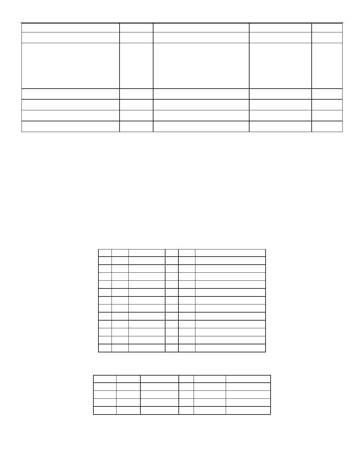
The following tables define these connector pin-outs:
Table 21. Main Power Connector Pin-out (J9H1)
Pin
IO
Signal Name
Pin
IO
Signal Name
1
PWR
+3.3V
13
PWR
+3.3V
2
PWR
+3.3V
14
PWR
-12V (NA for most designs)
3
GND
GND
15
GND
GND
4
PWR
+5V
16
I
PS_ON#
5
GND
GND
17
GND
GND
6
PWR
+5V
18
GND
GND
7
GND
GND
19
GND
GND
8
O
PWR_GD
20
NC
NC
9
PWR
SB5V
21
PWR
+5V
10
PWR
+12V
22
PWR
+5V
11
PWR
+12V
23
PWR
+5V
12
PWR
+3.3V
24
GND
GND
Table 22. CPU Power Connector Pin-out (J9B1)
Pin
IO
Signal Name
Pin
IO
Signal Name
1
GND
GND
5
PWR
P12V1
2
GND
GND
6
PWR
P12V1
3
GND
GND
7
PWR
P12V2
4
GND
GND
8
PWR
P12V2

Table of Contents

Questions and Answers:

Question and Answer IconNeed help?

Do you have a question about the Intel S1200SPL and is the answer not in the manual?

Intel S1200SPL Specifications

General IconGeneral
BrandIntel
ModelS1200SPL
CategoryServer Board
LanguageEnglish

Related product manuals