Intel® Server Board S1200SP Family Technical Product Specification
73
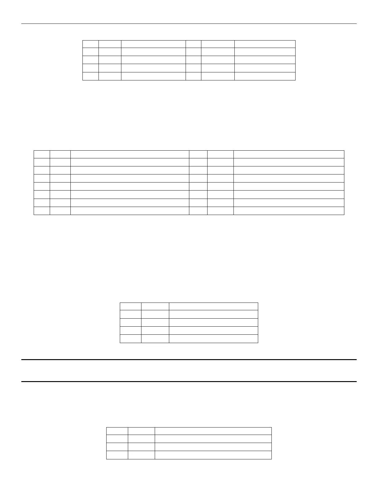
Table 26. Intel
®
RMM4 – Lite Connector Pin-out (J3B1)
8.3.2 TPM Connector
The Intel® Server Board S1200SPL and S1200SPO support TPM 2.0 module AXXTPMSPE6. The S1200SPS
server board does not support TPM 2.0 module.
Table 27. TPM Connector Pin-out (J8K1)
RST_BMC_NIC_LRESET_LVC3_R_N
8.3.3 Intel
®
ESRT2 RAID Upgrade Key Connector
The server board provides one connector to support Intel
®
ESRT2 RAID Upgrade Key. The I Upgrade Key is a
small PCB board that enables RAID 5 software stack of ESRT2 SW RAID. The pin configuration of connector is
identical and defined in the following table:
Table 28. Intel
®
ESRT2 RAID Upgrade Key Connector Pin-out (J9K1)
Note: The ESRT2 RAID 5 under legacy BIOS mode IS NOT supported.
8.3.4 HSBP SMBUS Header
Table 29. HSBP SMBUS Header Pin-out (J3K3)