Chapter 1 — Replacing Parts
CV30 Fixed Mount Computer Service Manual 23
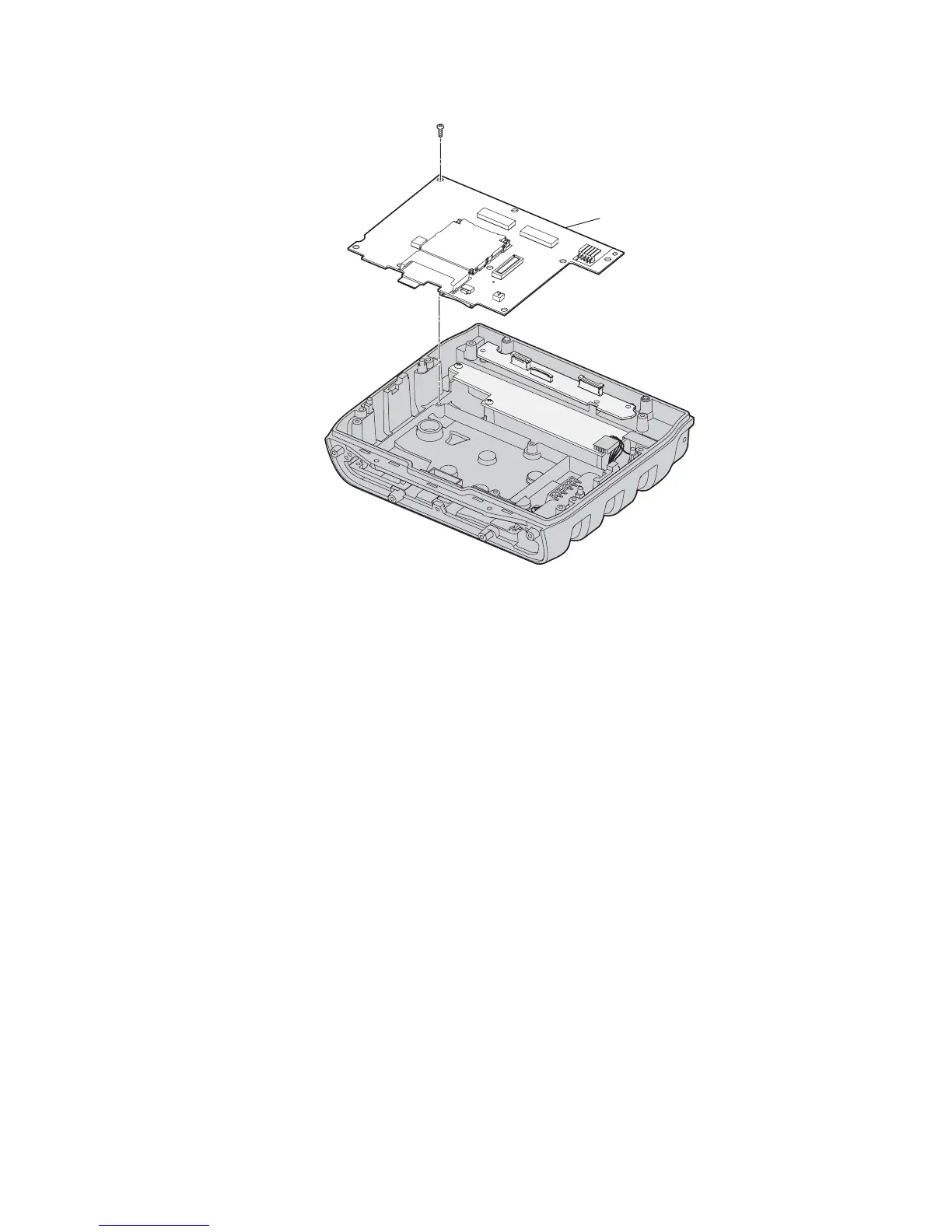
7 Insert the new main PCB and secure it with the seven 4-40 x 1/4 inch
Phillips screws.
8 Reattach the touch heater PCB harness, the I/O PCB harness, the
backup battery cable, and the power connection cable.
9 Reinsert the display frame and touch screen assembly and replace the
four 4-40 x 3/8 inch Phillips screws that attach it to the base assembly.
10 Reconnect the three flex connectors to the touch heater PCB.
11 Replace the front cover and secure it with the six 4-4- x 5/8 inch screws
and the two 4-40 x 3/8 inch screws removed previously and tighten to
.73 Nm (6.5 lb-in).
12 Reattach the antenna cable to the Remote Antenna connector on the
radome board assembly PCB.
13 Replace the top cover and secure it with the six 4-40 x 3/8 inch Phillips
screws removed previously and tighten to .62 Nm (5.5 lb-in).
14 Reconnect power to the CV30.
Screw
(7 places)
Main
PCB