Service Manual Invacare
®
Electra
As at: 15.04.02 Page 29
4.17
4.18
4.33
4.34
4.35
4.36
4.37
4.38
4.39
4.40
4.41
4.42
4.43
4.46
4.47
1
1
1
2
2
2
1
1
1
2
2
1
2
1
1
>Battery charge display
"ON/OFF" pilot light
Buzzer
Nut M3, self-locking
Spacer, 6,4 X 4 X 19,47
Bolt, M6 X 30
Horn switch
Keyswitch
Steering cover, bottom
Nut, M2
Spring washer, M2
Battery charging cable
Bolt, M6 X 12
"CHARGING SOCKET" sticker
Spanner set
4.20
4.21
4.22
4.23
4.24
4.25
4.26
4.27
4.28
4.29
4.30
4.31
4.32
1
2
2
2
1
1
1
1
1
2
1
1
1
Drive lever
Nut M3, self-locking
Drive lever rubber
Pin
Restoring spring
Plate
Bolt, M4 X 20
Spacer
Potentiometer support
Bolt , M4 X 0,7 X 10
Nut M4, self-locking
Potentiometer 5K
Bolt, M6 X 5
10.2.2 Preparations for reassembly
• Remove the seat unit (see chapter 9.1.5 page: 16).
• Remove clamp and seat tube (see chapter 9.1.6 page 16)
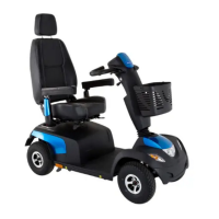
• Carefully pull the chassis panelling upwards off the Velcro connectors.
• Interrupt power supply. Battery cable (1).
Battery cable connector
plug
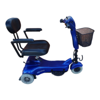
10.2.3 Reassembly sequence for "replacing steering column wiring
harness
• Remove steering cover (see chapter. 9.2 page: 17)
• Remove all cable binders on the steering column wiring harness.
• Disconnect all wiring harness connecting plugs at the controller (4) and the
power supply (5).
Plug at controller
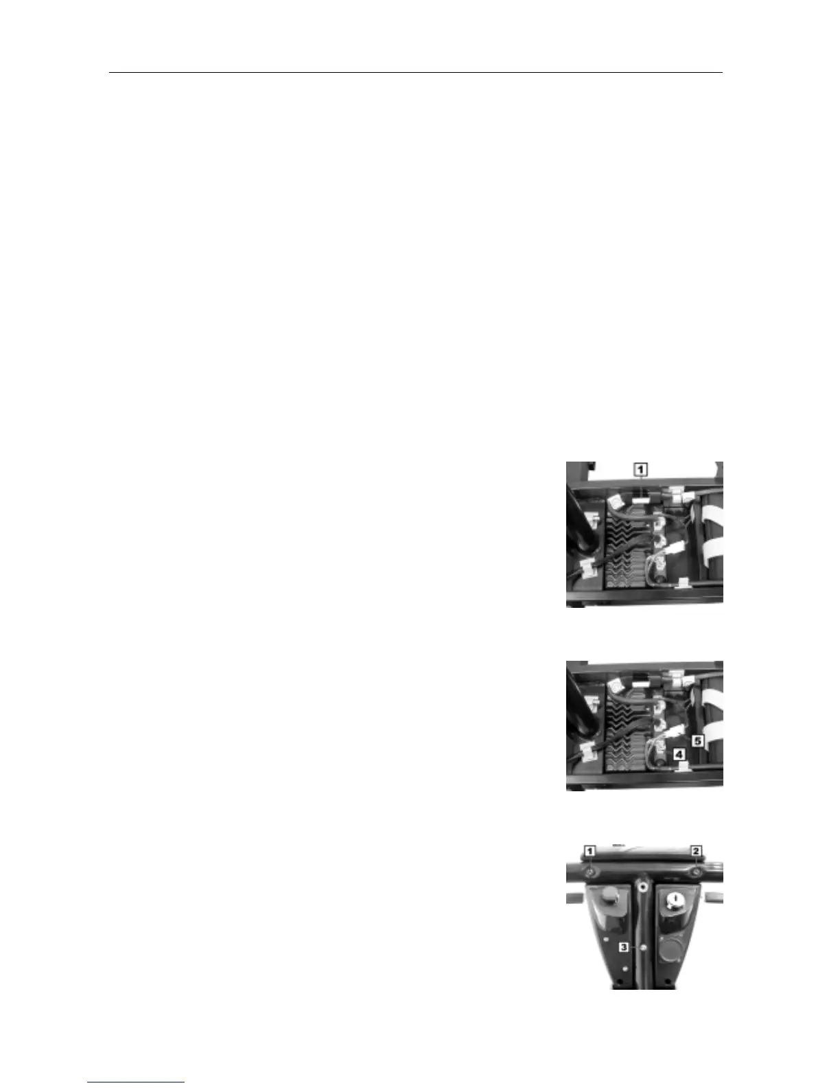
• Remove the operating unit from the handlebar. Three Phillips screws (1-3).
Fastening screws