BPD series PV pumping inverter Product overview
9
RUN/STOP button
COM
+24V
S2
J4
485
communication
J5
S3
S4
PE
Screen
Twisted pair
120Ω
485+
485-
Digital input 2
Screen
COM
Digital input 1
Digital input 3
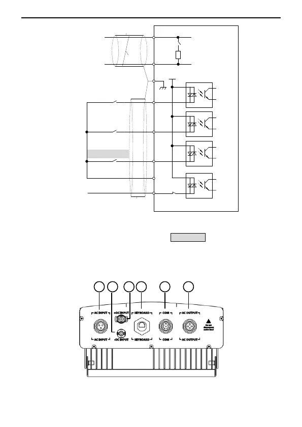
Figure 2.1 Control circuit wiring diagram
Note: For models of BPD2K2–5K5TRAC(S), the RUN/STOP button on the enclosure
corresponds to the S4 terminal,
2.5.2 Terminal arrangement
(a) BPD0K7–2K2TN(AC) terminals
 Loading...