BPD series PV pumping inverter Commissioning guide
65
frequency or water yield is low at normal light, the motor wires may be reversed, it
is necessary to set P00.13=1 or exchange the wiring of the motor. The operation
direction of 1PH motor whose capacitor is removed can only be changed by
function code.
5. Set the operation mode
After the water yield is normal and the system runs stably, set operation mode.
(1) Automatic operation: set P00.01=1, P05.01=1;
(2) Manual operation: set P00.01=1, P05.01=0 and P05.04=1, select S4 as the
start and stop control terminal, as shown in preceding wiring diagram. The
system can run only when S4 is switched on. For models of 380V, you can
press the "RUN/STOP" button on the enclosure to run the inverter,
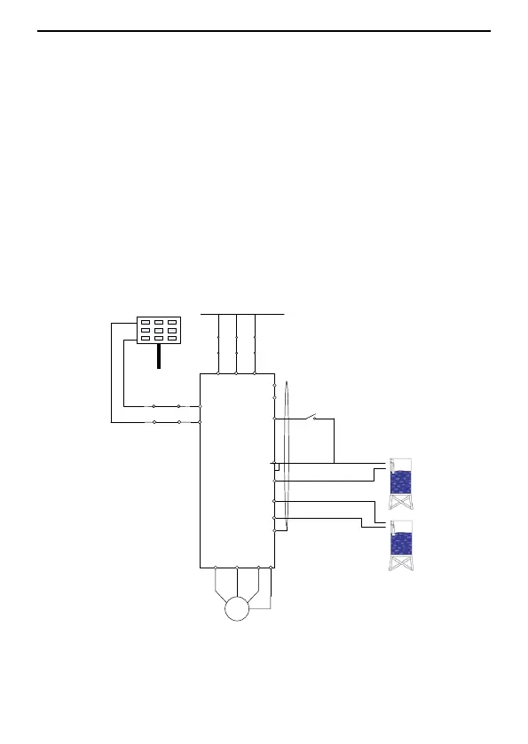
6.3 Commissioning on automatic switching between PV and grid
power supply
1. Perform the wiring according to the diagram and switch on Q1 and Q2.
Q2
PV solar panels
Q1
The grid
S4
PV+
PV pumping inverter
M
U V W
L N PE
CO
M
S2
S3
COM
PE
485-
485+
PV-
Run/Stop
Reservoir
PE
Full water signal
No-water signal
Figure 6.3 Wiring when both PV and grid power supplies are applied
2. Set the motor parameters
(1) Set P00.18=1 to restore the factory settings.
 Loading...