BPD series PV pumping inverter Product overview
12
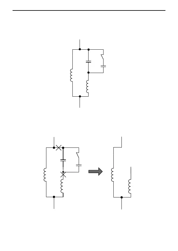
(if any). The wiring of a general motor is shown in Figure 2.3: L1 is the running winding,
L2 is the starting winding, C1 is the running capacitor, C2 is the starting capacitor, and
when the motor speed exceeds 75% of the rated speed, the starting capacitor is
switched off through the centrifugal switch K.
Figure 2.3 Internal wiring of the 1PH motor with starting and running capacitors
Figure 2.4 shows the internal wiring after the starting and running capacitors are
removed.
U1
U2
V2
V1
L1
L2
C1
C2
W
U
V
U1
U2
V2
V1
L1
L2
L
N
K
Figure 2.4 Wiring of a 1PH motor in 2PH control mode
U1 and V1 are the common terminal of the windings, and connect with the W output of
the PV pumping inverter, U2 of the running winding connect with the U output of the PV
 Loading...